3.3 Programming Mode
3-25
Chap. 3 OPERATION USING THE KEYPAD
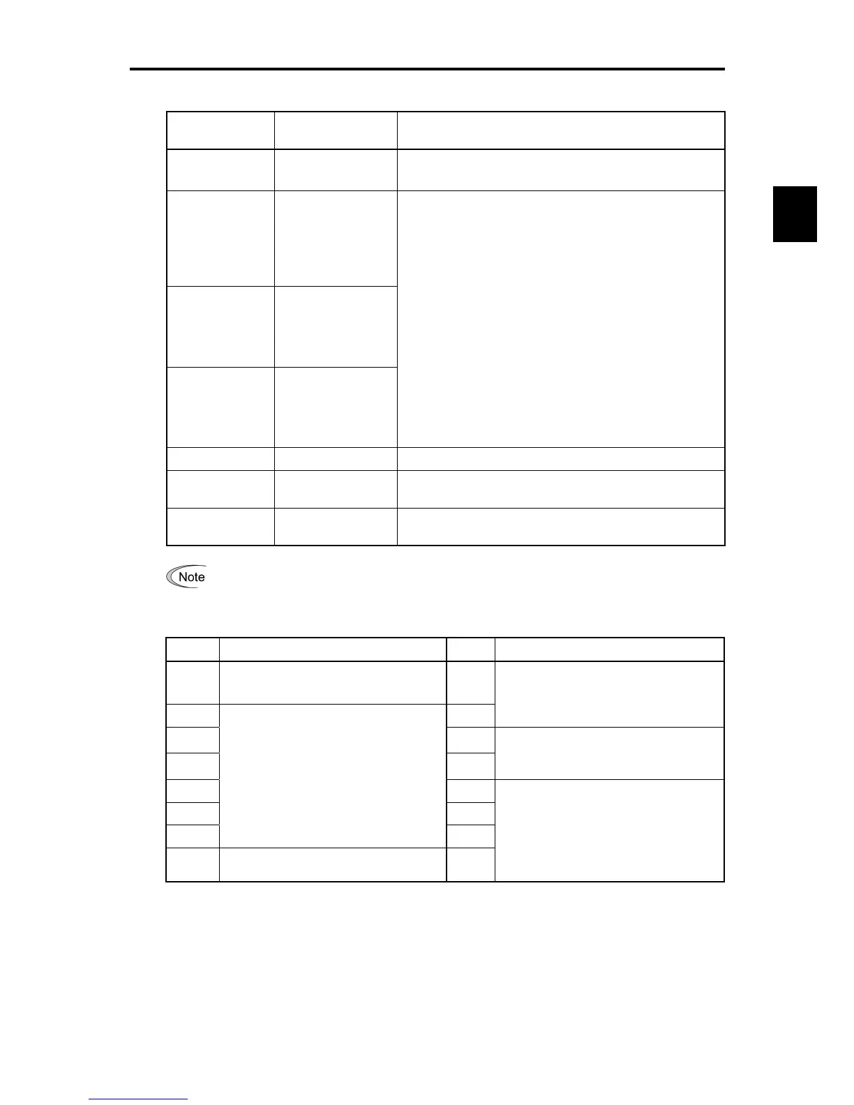
Table 3.13 Alarm Information Contents (Continued)
LED monitor
shows: (Item No.)
Display contents Description
6_17
Overlapping alarm 2 Simultaneously occurring alarm codes (2)
(– – – – is displayed if no alarms have occurred.)
6_18
Terminal I/O signal
status under
communication
control (displayed
with the ON/OFF of
LED segments)
6_19
Terminal input signal
status under
communication
control (in
hexadecimal format)
6_20
Terminal output
signal status under
communication
control (in
hexadecimal display)
Shows the ON/OFF status of the digital I/O terminals under
RS-485 communication control. Refer to Section 3.3.4 "[2]
Displaying control I/O signal terminals under communication
control" for details.
6_21
Error sub code Secondary error code for the alarm.
6_22
Running status 2 Shows the running status 2 in hexadecimal format. For details,
see the table below.
6_24
Running status 3 Shows the running status 3 in hexadecimal format. For details,
see the table below.
When the same alarm occurs a number of times in succession, the alarm information for the
first time is retained and the information for the following alarms is not updated.
Table 3.14 Running Status 2 (
6_22
) Bit Assignment
Bit Content Bit Content
15
Drive motor type
0: Induction motor,
1: Permanent magnet synchronous motor
7
14 6
(Not used.)
13 5
12 4
Motor selection
00: Motor 1
01: Motor 2
11 3
10 2
9
(Not used.)
1
8
Rotation direction limitation
0: Enable, 1: Disable
0
Inverter drive control
0000: V/f control with slip compensation
inactive
0001: Dynamic torque vector control
0010: V/f control with slip compensation
active

 Loading...


