6
2
Operations
2-1 Parameter list
Parameters for the PXR are classified under three blocks according to the frequency of use. The parameters of the second
and third blocks are used at initialization or when they are of absolute necessity.
Some parameters may not be displayed at the time of delivery depending on the type of the instrument.
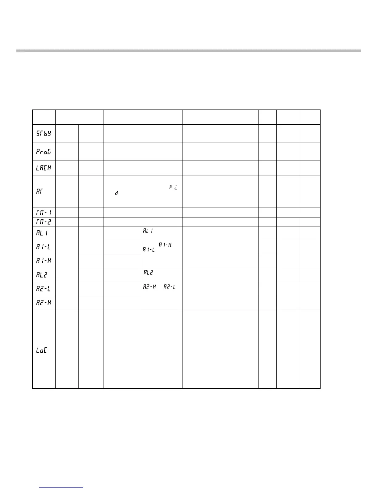
Parameters of the first block
This chapter explains how to set the SV (Setting value) and the parameters for the PXR.
Used for setting the constants for , ,
and by auto-tuning.
Stby
ProG
LACH
AT
TM-1
TM-2
AL1
A1-L
A1-H
AL2
A2-L
A2-H
LoC
Parameter
display symbol
User’s
set value
Reference
page
Parameter name
Description
Setting range and
factory default setting (*)
oN: Control standby
(Output: OFF, Alarm: OFF)
oFF: Control RUN*
oFF: Stop*
rUn: Start
HLd: Hold
0: Keeps the alarm latch.*
1: Opens up the alarm latch.
0: OFF (Resets the auto-tuning or does
not use it.)*
1: ON (Performs the auto-tuning in the
SV standard type.)
2: ON (Performs the auto-tuning in
low PV type (SV value-10%FS).)
- (Unit: seconds)
- (Unit: seconds)
When the alarm type is absolute value:
0 to 100%FS (*:10)
When the alarm type is deviation:
-100 to 100%FS (*:10)
When the alarm type is absolute value:
0 to 100%FS (*:10)
When the alarm type is deviation:
-100 to 100%FS (*:10)
0: All settings are changeable both from
the face panel and via communication.*
1: All settings are unchangeable from the
face panel, but changeable via
communication.
2: Only the SV is changeable from the
face panel, and all settings are
changeable via communication.
3: All settings are changeable from the
face panel, but unchangeable via
communication.
4:
All settings are unchangeable from the
face
panel or
via
communication.
5:
Only the SV is changeable from the
face
panel, but all settings are unchangeable
via
communication.
Parameter
mask DSP
dSP1-1
dSP1-2
dSP1-4
dSP1-8
dSP1-16
dSP1-32
dSP1-128
dSP2-1
dSP2-2
dSP2-4
dSP2-8
dSP2-16
dSP3-1
is displayed
when alarm type 1
is 0 to 15, or 32 to
34, and or
is displayed
when alarm type 1
is 16 to 31.
is displayed
when alarm type 2 is 0
to 15 or 32 to 34, and
or is
displayed when alarm
type 2 is 16 to 31.
13
14
15
16
17
17
18
18
18
18
18
18
19
*
*
*
*
*
*
Standby
setting
Ramp-soak
control
Alarm latch
cancel
Auto-tuning
Set value of
alarm 1
Lower limit
value of
alarm 1
Upper limit
value of
alarm 1
Lower limit
value of
alarm 2
Upper limit
value of
alarm 2
Key lock
Set value of
alarm 2
Timer 1 display
Timer 2 display
Switches between RUN and Standby
for control.
Switches between Start, Stop, and
Hold for ramp-soak control
Cancels the alarm latch.
Displays the remaining time of timer 1.
Displays the remaining time of timer 2.
Specifies whether or not to allow the
change of parameters.
Sets the value at which
alarm 1 is detected.
Sets the lower limit
value at which alarm 1
is detected.
Sets the upper limit
value at which alarm 1
is detected.
Sets the value during
which alarm 2 is
detected.
Sets the lower limit
value at which alarm 2
is detected.
Sets the upper limit
value at which alarm 2
is detected.
Note: The parameters for which * is marked with the page number in Reference page are related to Remedies
of “4” on page 70.

 Loading...


