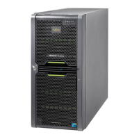
CHAPTER 2 PRIMEPOWER200 Pedestal Server
2.2.2 Control panel
The PRIMEPOWER200 Pedestal Server is provided with the control panel shown in Figure 2.3 .
REQUEST
RESET
CHECK
AUTO
POWER
POWER
MANUAL SECURE
(1) RESET Switch
(2) MODE Switch
(3) REQUEST Switch
(4) LCD Panel
(5) POWER Switch
(6) CHECK LED (Amber)
(7) POWER LED (Green)
Figure 2.3 Control Panel
Note: To prevent erroneous operation, all push-button switches on the control panel are designed not to
function unless held down for at least 0.3 seconds.
(1) RESET switch (push button)
CAUTION
Data Destruction
Pressing the RESET switch while the system is running may cause
data to be lost.
The RESET switch is used to reset the system to its initial state and is enabled or disabled by the
MODE switch described in "(2) MODE Switch".
(2) MODE switch (3-position slider)
CAUTION
Data Destruction
Install the "Enhanced Support Facility" before using the system.
Without this package, a front panel-miss operation or hardware
error may cause the system to shutdown or data to be lost.
The MODE switch has three settings and is used to specify the run mode at power on or system
reboot, and to whether the POWER, RESET and REQUEST switches are "enabled" or "disabled".
Table 2.1 MODE Switch Settings
MODE
switch
POWER
switch
RESET
switch
REQUEST
switch
Operation mode
MANUAL
AUTO
SECURE
Enabled
Enabled
Enabled Enabled
Disabled Disabled Disabled
Disabled Disabled
The OS is automatically booted after initial
diagnostics are completed. The TTY terminal
"break" and keyboard "STOP+A" commands
are disabled while Solaris is operating.
The OS is automatically booted after initial
diagnostics are completed.
The bootup sequence stops at an ok prompt
after initial diagnostics are completed.
Use this mode to enter commands and make
settings from the ok prompt when performing
maintenance on the server unit.
6

 Loading...


