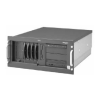
CHAPTER 3 PRIMEPOWER200 Rackmount (4U) Server
Table 3.3 Installation Specifications of the PRIMEPOWER200 Rackmount (4U) Server (2/2)
Unit
Top
Side
Service
Area
Rear
Service
Area
Front
Service
Area
745 (*1) (D)
(29 in.)
Unit Side
Item Specification
800
(32 in.)
800
(32 in.)
800
(32 in.)
Side
Service
Area
800
(32 in.)
Unit Dimensions
(units : mm)
Service Areas
(units : mm)
Unit Front
445 (*1) (W)
(18 in.)
174 (H)
(7 in.)
Pull-Out
Area
(*2)
1000
(39 in.)
905 (*3)
(36 in.)
650 (*3)
(26 in.)
*1: Not including any projections.
*2: Keep the pull-out area clear so that devices inside the PRIMEPOWER200 Rackmount (4U) Server
can be pulled out from the rack cabinet when performing maintenance.
*3: When a GP7B7RK3x/RK4x rack cabinet is used
3.3.3 Connecting the console
A device such as a personal computer must be connected to the serial port to act as the console for a
PRIMEPOWER200 Rackmount (4U) Server to which a display or keyboard is not connected. Pay attention to the
following when connecting the console to the serial port on the PRIMEPOWER200 Rackmount (4U) Server.
Connect the serial cable:
Connect to serial A port.
Communication settings on the terminal:
Set to 8 bits, 1 stop bit, parity OFF, and 9600 baud.
34

 Loading...


