Do not cut the cable tie.
▶
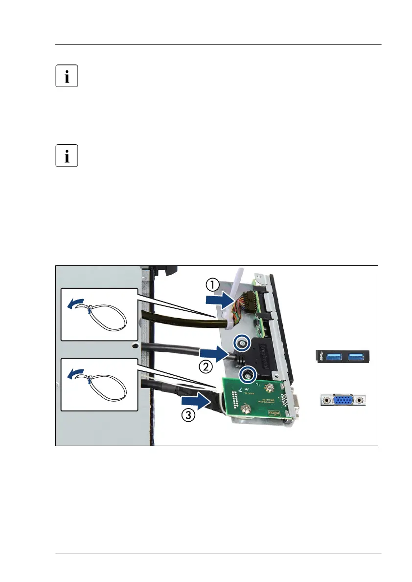
Remove the two corresponding screws and disconnect the front USB cable
(2).
▶
If applicable, open the cable tie and disconnect the front VGA cable (3).
Do not cut the cable tie.
▶
If applicable, remove the front VGA board with the front VGA connector, see
"Removing the front VGA board" on page
275.
Installing the front panel module
▶
If applicable, install the front VGA board with the front VGA connector, see
"Installing the front VGA board" on page 273.
Figure 183: Connecting cables to the front panel module
▶
Connect the front panel cable and secure it with the cable tie (1).
▶
Push the front USB connector in the corresponding recess and fasten the
front USB cable with two screws (2)
Front panel
RX1330 M4 Upgrade and Maintenance Manual 271

 Loading...