U41057-J19-Z146-1-76 July 2004 02–TX150S2–105
Removal/installation routines Boards in PCI slots
© Siemens Nixdorf Informationssysteme AG 1995 Pfad: P:\02-systemeinheiten\TX150S2\TX150S2-e\TX150S2-e.k04
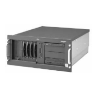
Ê Press in direction of the arrow (1) on the clamp fix and remove it (2).
Ê Pull out the board of the slot (3).
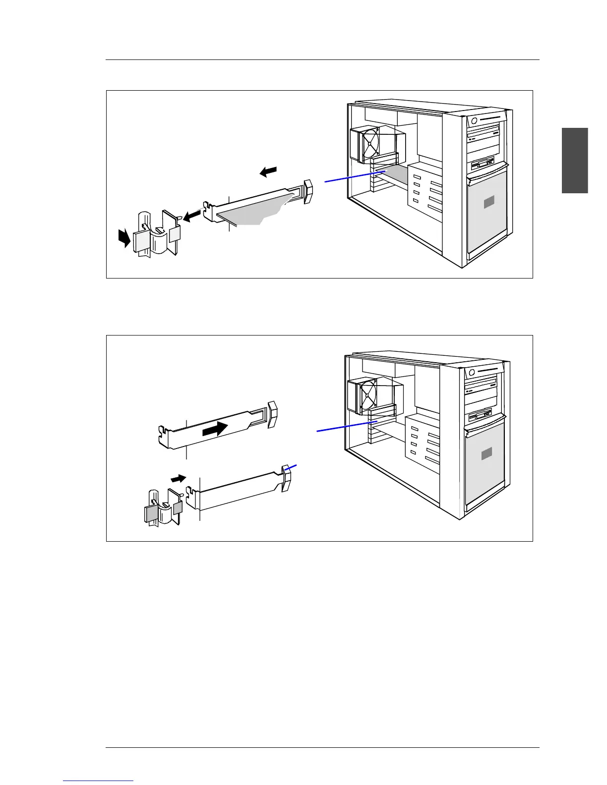
Ê Insert the rear slot cover plate into the empty slot (1). Make sure that the rear
slot cover plate is positioned in the groove (a).
Ê Insert the climb fix for fastening the rear slot cover plate as shown (2). Make
sure that the climb fix engages in the housing.
2
1
3
a
1
2
 Loading...