U41057-J19-Z146-1-76 July 2004 02–TX150S2–129
Removal/installation routines Power supply
© Siemens Nixdorf Informationssysteme AG 1995 Pfad: P:\02-systemeinheiten\TX150S2\TX150S2-e\TX150S2-e.k04
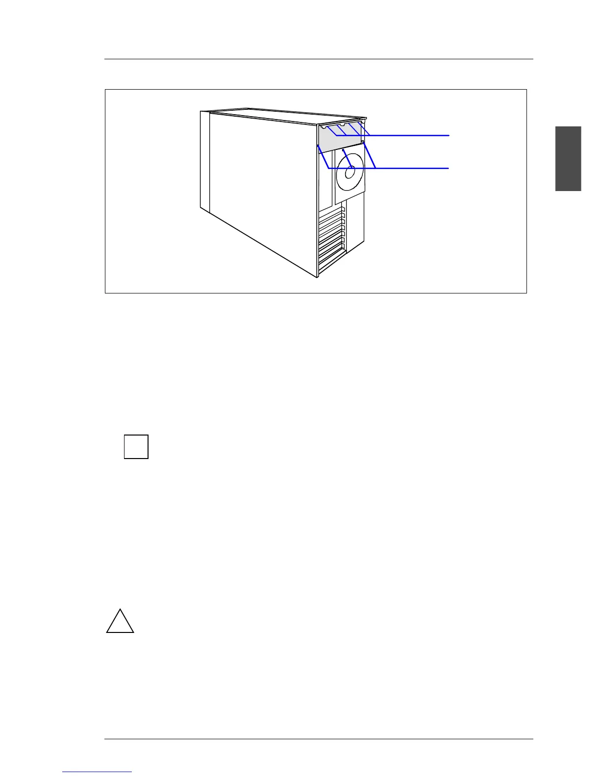
Ê Fix the locking rail with four screws (1) on the rear side of the server.
Ê Fix the power supply cage with three screws (2).
Ê Connect all boards and devices to the new power supply. For the cabling see
page 02-TX150S2-59.
Ê Reinstall the air duct.
Ê Insert the power supply module.
The redundant power supply module automatically adjusts to the
proper voltage range.
Ê Install the dummy module.
Ê Close the server.
Ê Mount the anti-tilt bracket (see page 02-TX150S2-20).
Ê Connect the power supply module to a grounded power outlet with the power
cable supplied.
You will find the description of the indicators of the power supply module on
page 02-TX150S2-36.
After installing the redundant power supply the SDR (sensor data record)
data base must be updated. For this sequence you need the BIOS flash
diskette prepared before. This diskette contains the newest BIOS
version, the BMC firmware and the SDR data.
2
1
i
!
 Loading...