U41057-J19-Z146-1-76 July 2004 02–TX150S2–67
© Siemens Nixdorf Informationssysteme AG 1995 Pfad: P:\02-systemeinheiten\TX150S2\TX150S2-e\TX150S2-e.k03
02
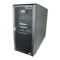
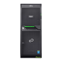
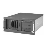
TX150S2
Diagnostics
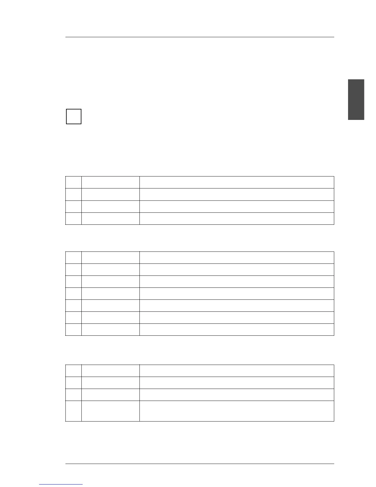
Assignment of the components in ServerView
Because of the different numbering depending on the server configu-
ration, you find in the following an example for the maximum configu-
ration and the field purpose will be described to identify the component.
Fans
Standard power supply:
Redundant power supply:
(each power supply module has two fans)
Temperature sensors
No. Purpose Description
0 FAN CPU CPU fan (speed can be controlled)
1 FAN STD PSU Fan standard power supply
2 FAN SYS System fan (speed can be controlled)
No. Purpose Description
0 FAN CPU CPU fan (speed can be controlled)
1 FAN SYS System fan (speed can be controlled)
2 FAN RED PSU0 Fan 1 of the first power supply module
3 FAN RED PSU0 Fan 2 of the first power supply module
4 FAN RED PSU1 Fan 1 of the second power supply module (optional)
5 FAN RED PSU1 Fan 2 of the second power supply module (optional)
No. Purpose Description
0 Systemboard Temperature sensor on the system board (onboard)
1 CPU Temperature sensor CPU (integrated in CPU)
2 Ambient Environment temperature, temperature sensor on the IDTEMP
combo, position is behind front panel, under the hard disks
i
 Loading...