CS875-575-375-275-175 Installers Manual with CS5500 keypad B.16.1
Chapter 16: Setting up the CS7501
16.1 Overview
The CS7501 ISDN (integrated services digital network) dialler allows digital data to be sent over a standard
phone line. It supports reporting over the B and D channels on ISDN.
16.2 Installing the CS7501 ISDN dialler
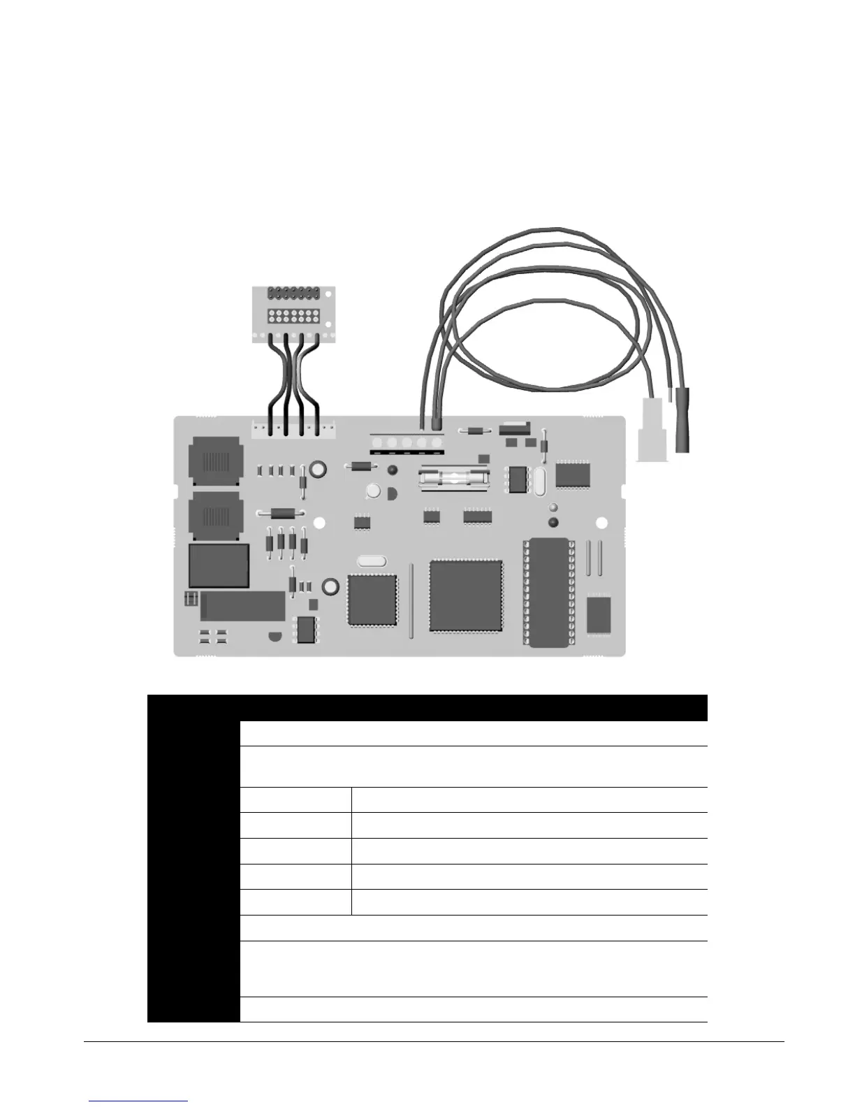
Part Purpose
J1 ISDN connector to receive the incoming signal.
J2/J3 Bi-directional connector to the control panel. It connects the audio circuits to the control panel and
CS534 to provide up/download and audio listen-in.
J4 1 DAT Connects to the DATA connection on the control panel
2 COM Connects to the COM connection on the control panel
3 POS Connects to the AUX+ connection on the control panel
4 COM Power connection using the black battery lead.
5 PWR Power connection using the red battery lead.
J5 ISDN connector for the outgoing signal.
JP2/JP3 ISDN terminating resistors. The total impedance of the S0-bus should be 50 Ohm. The 2 jumpers
JP2/3 should only be placed when the "priority relay" is used and when you have no EOL resistors
on a device other than the CS7501.
D11 Green LED ISDN communication status.
J1
J2
J3
JP2/3
J4
D11
J5
D13