CS875-575-375-275-175 Installers Manual with CS5500 keypadA.4.17
4.7 Control unit wiring diagrams
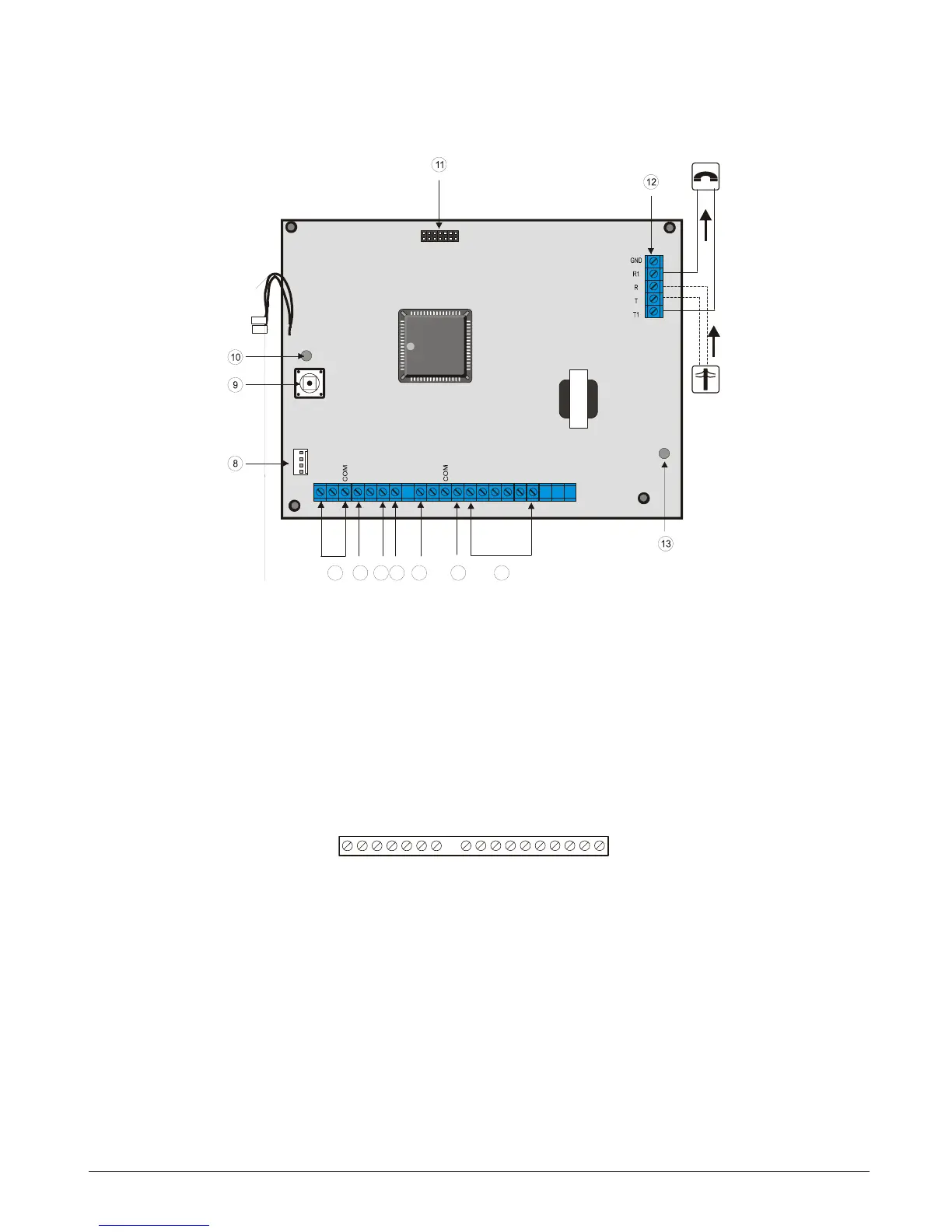
4.7.1 CS175
4.7.1.1 Inputs and outputs
1
Zones 1-4
6
External sounder
B
Serial expansion
2
Box tamper input
7
Keypad bus
C
Phone line connector
3
Fire detector reset output
8
Additional keypad bus connection
D
Phone line communication LED
4
Open collector 2
9
Lid tamper
5
Open collector 1
A
Bus supervision LED
DATA Communication/Expander data (0101) (including keypad) COM Ground
AUX + Communication/Expander power (including keypad) TAMPER Tamper loop
COM Communication/Expander ground (including keypad) Z1 Zone 1
EXT External bell return COM Ground
COM Ground Z2 Zone 2
OUT 1 Output 1 Z3 Zone 3
OUT 2 Output 2 COM Ground
SMOKE Fire detector reset output Z4 Zone 4
AUX + Power
J14
RED
J15
BLACK
.
.
J16
J1
COM
Z2
Z3
Z1
Z4
DATA
AUX+
COM
EXT
O
U
T
2
A
U
X
+
C
O
M
T
A
M
P
E
R
S
M
O
K
E
O
U
T
1
5
7 6
4
3
2 1
S1
J17
EXPANSION
LED 2
LED 3
DATA
AUX+
COM
E
X
T
C
O
M
O
U
T
1
O
U
T
2
S
M
O
K
E
A
U
X
+
C
O
M
T
A
M
P
E