4 TruVision DVR 40 User Manual
H. Connect the network devices.
I. Connect the USB mouse (supplied).
J. Connect the E-SATA for archive and storage expansion.
K. Terminate the line using this RS-485 switch. The default setting is OFF.
L. Connect the external data and alarm input/output (I/O) cable. See Figure 3 on page 4 for more information.
M.
Connect the TVR 40 to ground.
Power connection
N. Connect the power cord to the TVR 40. Be sure all devices are connected and turned on before you turn on the
TruVision DVR 40.
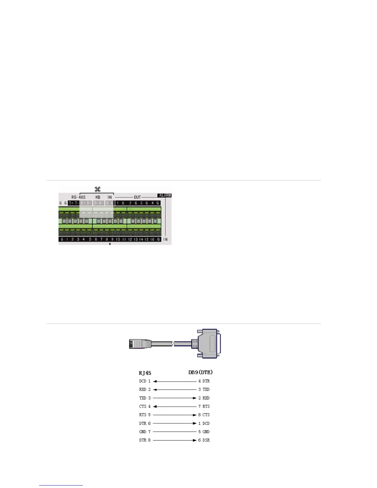
Connecting alarm inputs and outputs
Figure 3: Connecting the external data and alarm I/O cable
: Not used
RS-485 T+ T-: Connect PTZ camera data
Alarm output port:
1-G to 4-G: 4 relay ports
Alarm input port:
G: Common ground)
1 to 16: Alarm inputs, NO/NC supported
Connecting the TVR 40 to a PC
Use a RS-232 cable to connect the unit to a PC. Figure 4 describes the pin connections to use when
connecting the serial port of the TVR 40 to a device using a DB9 connector such as on a PC.
Figure 4: The pin connections of a RS-232 cable
TVR 40
PC
Pin configuration