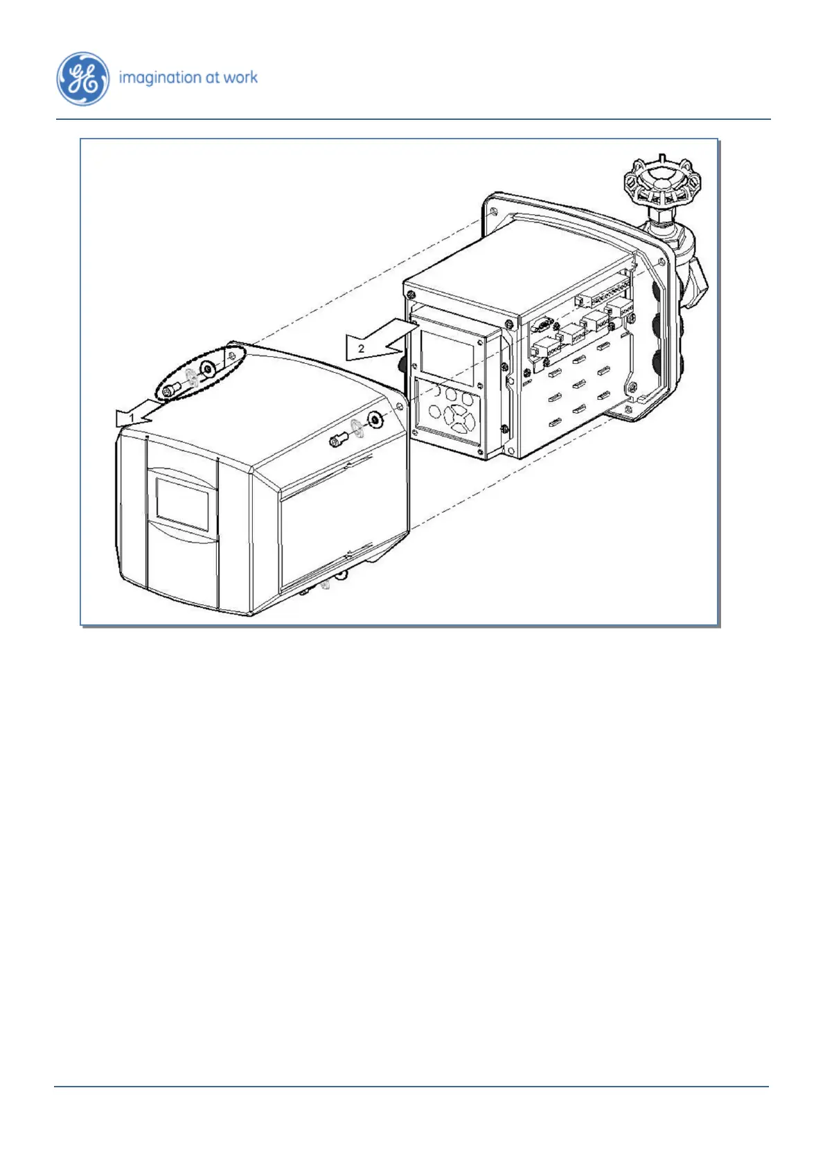
Figure 4-11: Removing the Hydran M2-X Cover
4. Mount a conduit to each conduit fitting. Cables connected to terminal blocks
located on one side of the Hydran M2-X must pass through a conduit fitting
mounted on the same side. When possible, more than one cable can be run in
a single conduit. The following cables can be run (for the location of each
terminal block, see Figure 2-5 and Figure 2-6):
• Hydran M2-X’s left side (when facing the display):
– ac power supply cable.
– Alarm contacts cable (connected to a SCADA system)
• Hydran M2-X’s right side:
– Input cable of the RS-485 link (connected to another Hydran M2-X).
– Output cable of the RS-485 link (connected to another Hydran M2-X or
to a Hydran 2901Ci-C controller).
– Up to four optional cables for I/O (analog inputs and/or outputs).
5. Ground the conduits and/or cable shields at some point. Follow the company
regulations meticulously. To ground the conduit of the RS-485 cable, see
Section 5.2.