Hydran* M2-X Instruction Manual
MA-029 Rev. 1.0, 30-Jul-18
4.3.5 Installing the Sensor onto the Valve
The sensor has 1.5 in (approximately 38 mm) NPT male threads to screw onto the
valve. If an adaptor is not required to mount the sensor onto the valve, skip steps 1
to 3.
1. If using a finned, high-temperature adaptor, a thin layer of thermal joint
compound must be applied on the outside of the mounting adaptor before
assembling all parts; remove excess of compound with solvent.
2. Wrap PTFE tape on the adaptor’s threads.
Use only PTFE tape to seal the adapter’s threads. Wrap at
least four to five layers of tape around the threads.
3. Screw the adaptor onto the valve and tighten it using an adjustable wrench.
Never use a wrench with jagged jaws.
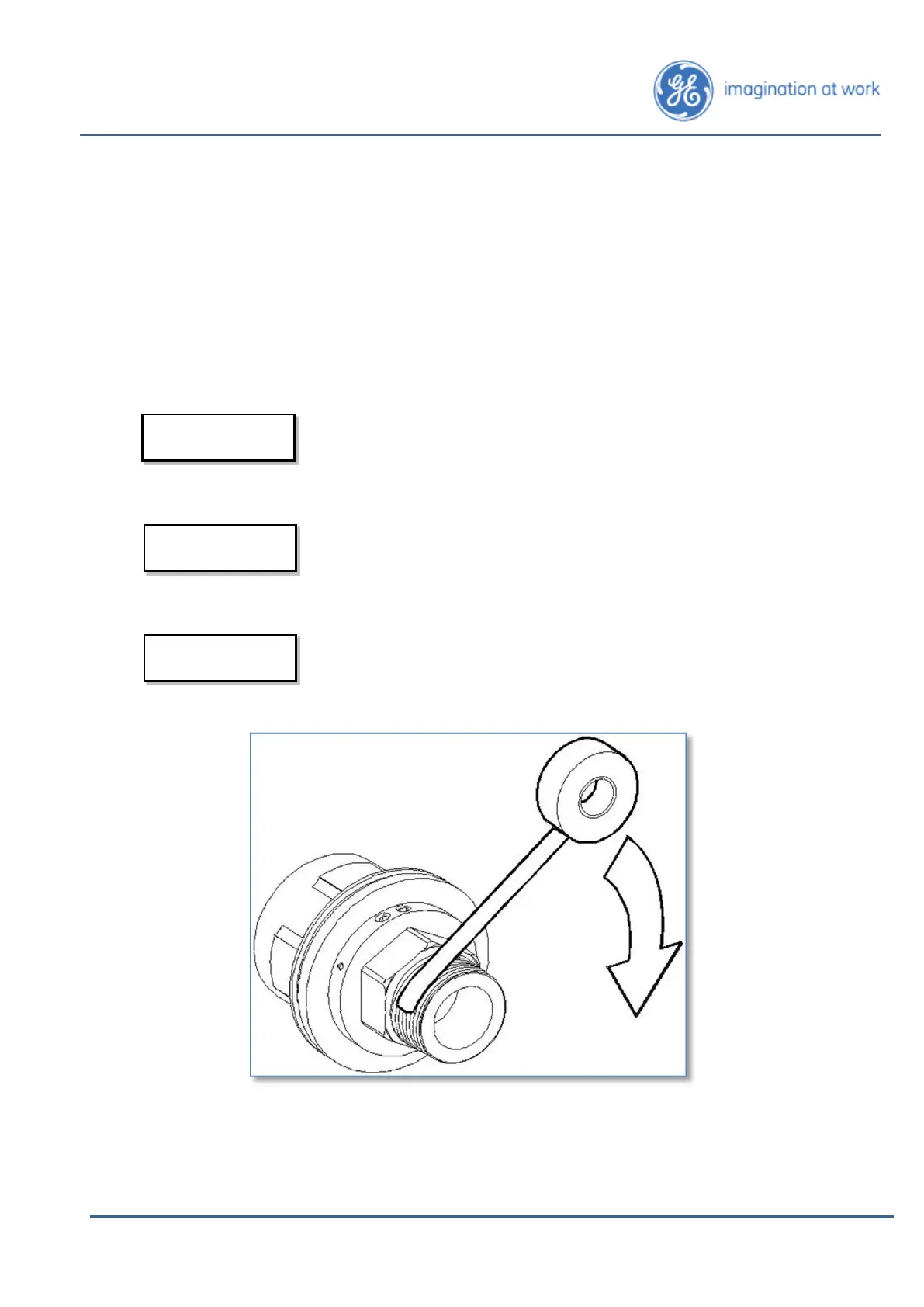
4. Wrap PTFE tape on the sensor’s threads. See Figure 4-5.
Use only PTFE tape to seal the sensor’s threads. Wrap at
least four to five layers of tape around the threads.
Figure 4-5: Wrap the Sensor’s Threads with PTFE
5. Loosen the bleed screw.
6. Install the sensor clamp around the sensor. See Figure 4-6 overleaf.
Always wrap the tape counter to
the threads, as shown here.