Appendix E. Installing I/O Modules
Note: Installing I/O modules requires only a Phillips screwdriver.
Proceed as follows:
1. Remove the four screws holding in place the Hydran M2-X cover and remove
this cover. See Figure 4-11.
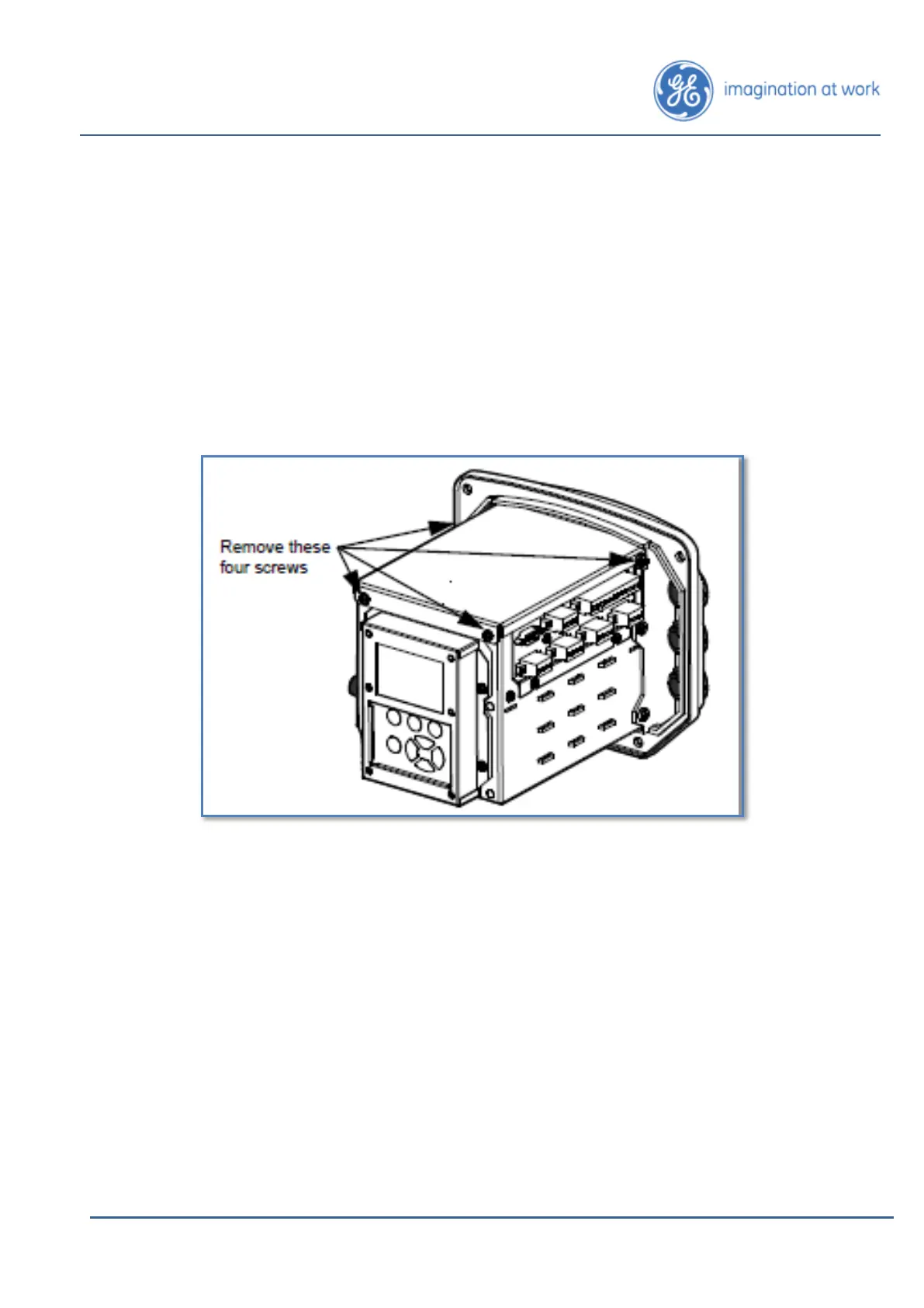
2. Remove the four screws holding in place the cover plate of the electronic card
cage and remove this plate. See Figure E-1 below.
Figure E-1: Opening the Electronic Card Cage
3. Carefully disconnect connectors J10, J11, J13 and J14.
4. Remove the four screws holding in place the controller board.
5. Remove the two screws holding in place the I/O assembly, and remove the
I/O assembly from the electronic card cage. See Figure E-2 on the next page.
6. Secure each I/O interface in one of the four locations using the following
parts:
• Two screws (PAN, 6-32, 5/16, SS, Phillips; part number 16423).
• Two washers (flat, #6, ID = 0.143, OD = 0.267, SS; part number 16445).
• Two lock washers (#6, SP/SP, W2024; part number 12085).
7. Put back the I/O assembly in the electronic card cage. Reinstall the two
screws removed during step 5. See Figure E-2.
8. Carefully reconnect connectors J10, J11, J13 and J14.
9. Put back and tighten the four screws holding the controller board in place.