EasyManuals Logo

GE Hydran M2-X User Manual

GE Hydran M2-X
204 pages
To Next Page IconTo Next Page
To Previous Page IconTo Previous Page
Page #170 background imageLoading...
Page #170 background image
Hydran* M2-X Instruction Manual
Page 170
MA-029 Rev. 1.0, 30-Jul-18
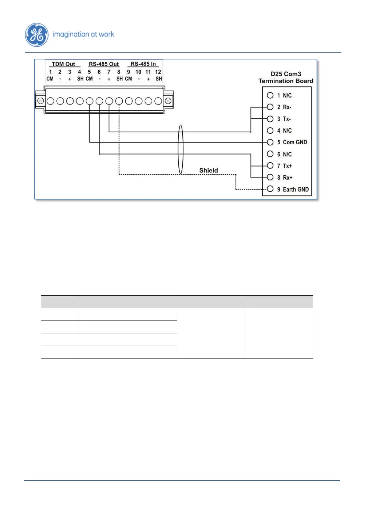
Figure D - 6: Wiring of the RS-485 Network Link between a Hydran M2-X and a D25
D-2. Analog Input Terminal Block
Table D-2 describes the connections for the analog input terminal block. This
terminal block is located on the right side of the electronic card cage (see Figure D-7
on the next page).
Terminal
Description
From (External)
Comments
1
Power
External sensor
(typically a top oil
temperature or
load current
sensor)
a
4-20 mA general
purpose input;
1,500V rms
isolation level
2
4-20 mA analog input-
3
4-20 mA analog input+
4
Shield
Table D - 2: Connections for the Analog Input Terminal Block
a. Magnetic-mount temperature and current sensors are available at General Electric. See Figure D-8 to
Figure D-10 on the following pages.
The recommended cable is: instrumentation grade, individually twisted and
shielded pairs or triads of copper multi-stranded wires, with a shield, a steel armor
and a PVC overall jacket.

Table of Contents

Other manuals for GE Hydran M2-X

Questions and Answers:

Question and Answer IconNeed help?

Do you have a question about the GE Hydran M2-X and is the answer not in the manual?

GE Hydran M2-X Specifications

General IconGeneral
BrandGE
ModelHydran M2-X
CategoryMeasuring Instruments
LanguageEnglish

Related product manuals