GE MEDICAL SYSTEMS
2127661
LOGIQ 400 SERVICE MANUAL
SYSTEM CONFIGURATION
3–8
REV 9
3–5–1 Peripherals/Accessories Connector Panel (Continued)
Note
The Ethernet Port (
6
in ILLUSTRATION 3–4) for the DICOM connection is available on the console
with the software version 3.40 or later and the optional DICOM Upgrade Set.
Note
Each outer (case) ground line of peripheral/accessory connectors are protectively grounded.
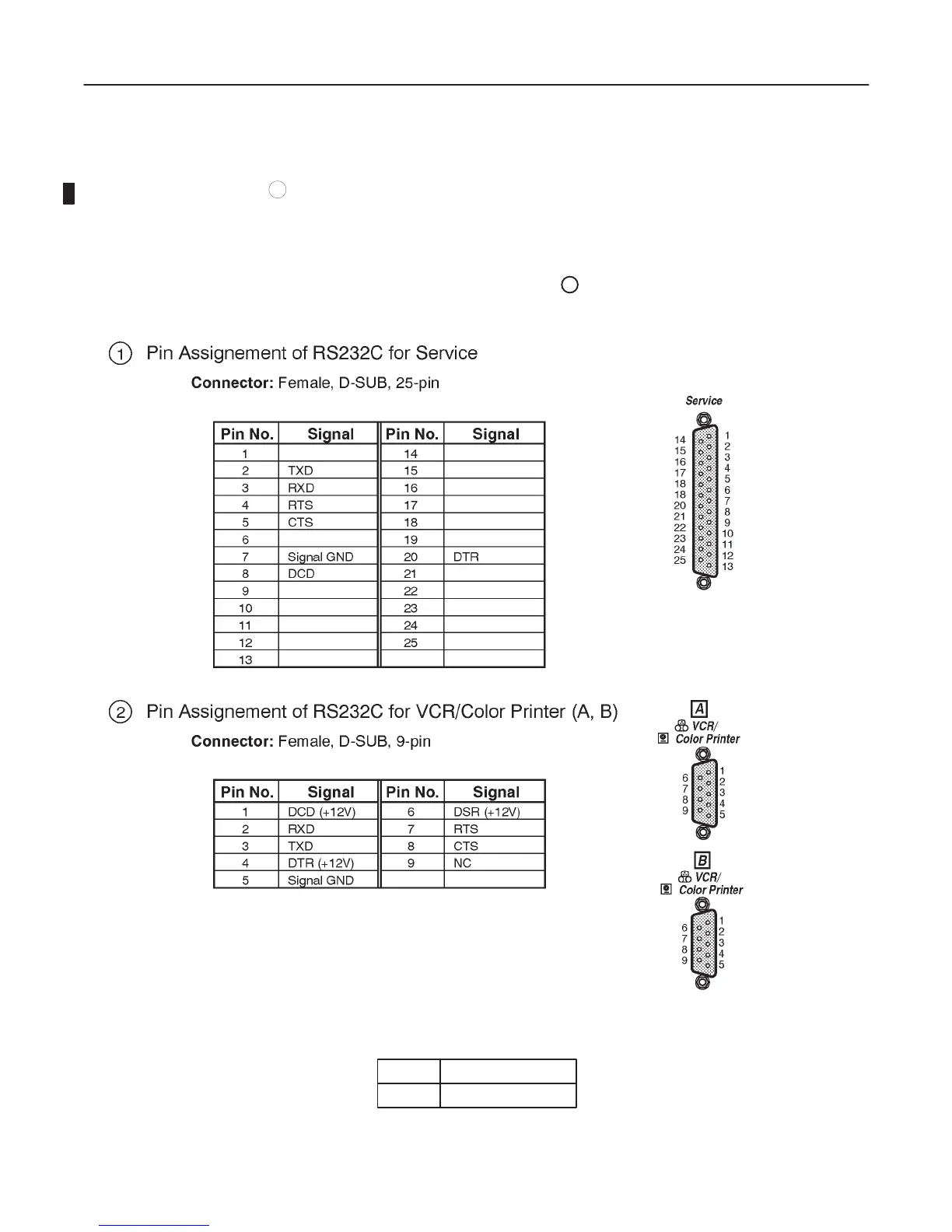
Signal ground lines are Not Isolated, except the Service port (
1
). All of signal lines (include signal
GND) of the Service port are isolated.
Note
Output level of RS232C signals:
High +3V to +15V
Low –15V to 0V

 Loading...


