DIRECTION 5750007-1EN, REV. 1 LOGIQ E10 BASIC SERVICE MANUAL
8 - 92 Section 8-7 - Replacing Top Console Parts
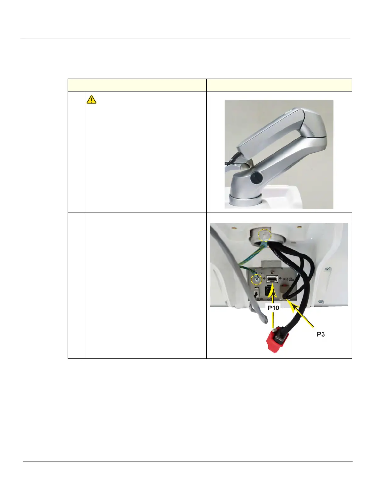
Monitor Arm assembly removal
This procedure assumes that the Monitor and Bulkhead Cover have been removed.
Table 8-107 Monitor Arm assembly removal
Steps Corresponding Graphic
1.
WARNINGWARNING
WHEN REMOVING THE MONITOR ARM,
KEEP THE ARM LOCKED, AS SHOWN
TO ENSURE THE MONITOR ARM
ASSEMBLY IS IN THE LOCKED
POSITION UNTILL THE ARM AND
MONITOR ARE INSTALLED. THE
SPRINGS TO SUPPORT THE MONITOR
CAN CAUSE THE ARM TO SPRING
OPEN CAUSING SEVERE PERSONAL
INJURY AND PROPERTY DAMAGE.
2.
Disconnect the Power Cable (P3) and the
HDMI (P10) from the Bulkhead Board.