DIRECTION 5750007-1EN, REV. 1 LOGIQ E10 BASIC SERVICE MANUAL
Chapter 8 Replacement Procedures 8 - 253
Section 8-11
Front End Acquisition / Card Cage parts replacement
8-11-1 Purpose of this section
This section describes how to replace the parts in the Front End / Card Cage.
Contents in this section
8-11-1 Purpose of this section . . . . . . . . . . . . . . . . . . . . . . . . . . . . . . . . . . . . . . . . . . . . . . . . . .8-253
8-11-2 Front End Card Rack parts overview . . . . . . . . . . . . . . . . . . . . . . . . . . . . . . . . . . . . . . . 8-254
8-11-3 Front End Card Cage Cover replacement . . . . . . . . . . . . . . . . . . . . . . . . . . . . . . . . . . . 8-255
8-11-4 Front Plane / XD BUS replacement . . . . . . . . . . . . . . . . . . . . . . . . . . . . . . . . . . . . . . . . 8-259
8-11-5 Relay Board (GRLY or RLY) replacement . . . . . . . . . . . . . . . . . . . . . . . . . . . . . . . . . . . 8-263
8-11-6 Transmitter Board (ETX) replacement . . . . . . . . . . . . . . . . . . . . . . . . . . . . . . . . . . . . . . 8-266
8-11-8 ECB replacement . . . . . . . . . . . . . . . . . . . . . . . . . . . . . . . . . . . . . . . . . . . . . . . . . . . . . .8-272
8-11-9 GPU replacement. . . . . . . . . . . . . . . . . . . . . . . . . . . . . . . . . . . . . . . . . . . . . . . . . . . . . .8-278
8-11-10 WLAN replacement . . . . . . . . . . . . . . . . . . . . . . . . . . . . . . . . . . . . . . . . . . . . . . . . . . . . 8-286
8-11-11 BIOS Battery replacement . . . . . . . . . . . . . . . . . . . . . . . . . . . . . . . . . . . . . . . . . . . . . . . 8-292
8-11-12 EPM replacement . . . . . . . . . . . . . . . . . . . . . . . . . . . . . . . . . . . . . . . . . . . . . . . . . . . . . .8-295
8-11-13 Backplane replacement . . . . . . . . . . . . . . . . . . . . . . . . . . . . . . . . . . . . . . . . . . . . . . . . . 8-298
8-11-14 Connector Panel replacement . . . . . . . . . . . . . . . . . . . . . . . . . . . . . . . . . . . . . . . . . . . . 8-314
8-11-15 Rear I/O replacement . . . . . . . . . . . . . . . . . . . . . . . . . . . . . . . . . . . . . . . . . . . . . . . . . . .8-327
8-11-16 Batteries replacement. . . . . . . . . . . . . . . . . . . . . . . . . . . . . . . . . . . . . . . . . . . . . . . . . . .8-330
8-11-17 HDD replacement . . . . . . . . . . . . . . . . . . . . . . . . . . . . . . . . . . . . . . . . . . . . . . . . . . . . . .8-335
8-11-18 Fan Tray replacement. . . . . . . . . . . . . . . . . . . . . . . . . . . . . . . . . . . . . . . . . . . . . . . . . . .8-339
8-11-19 Light Block (Hard Drive/Network Status) replacement . . . . . . . . . . . . . . . . . . . . . . . . . . 8-342
8-11-20 Printer Tray replacement . . . . . . . . . . . . . . . . . . . . . . . . . . . . . . . . . . . . . . . . . . . . . . . . 8-345
8-11-21 Cable Holders - ECB, Main Power Supply and Rear I/O replacement. . . . . . . . . . . . . . 8-348
8-11-22 Option Box replacement. . . . . . . . . . . . . . . . . . . . . . . . . . . . . . . . . . . . . . . . . . . . . . . . . 8-352
8-11-23 Card Cage replacement. . . . . . . . . . . . . . . . . . . . . . . . . . . . . . . . . . . . . . . . . . . . . . . . . 8-361
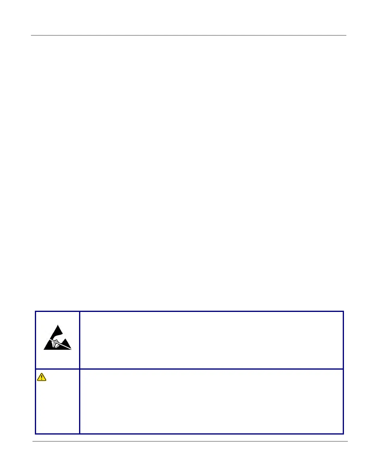
DO NOT TOUCH ANY BOARDS WITH INTEGRATED CIRCUITS PRIOR TO TAKING THE
NECESSARY ESD PRECAUTIONS:
1. ALWAYS CONNECT YOURSELF
. THE ESD WRIST STRAP SHOULD BE CONNECTED TO
ONE OF THE TWO RECEPTICALS INTEGRATED ON THE FRAME, SPECIFICALLY FOR THAT
PURPOSE.
2. FOLLOW GENERAL GUIDELINES FOR HANDLING OF ELECTROSTATIC SENSITIVE
EQUIPMENT.
WARNIN
WARNIN
Risk of electrical shock, system must be turned off. Avoid all contact with electrical contacts,
conductors and components. Always use non-conductive handles designed for the removal
and replacement of ESD sensitive parts. All parts that have the potential for storing energy
must be discharged or isolated before making contact.
IF THE SHEAR WAVE OPTION IS PRESENT, MAKE SURE THE LEDS ON THE CAPACITOR
PACK ARE OFF.
Prior to removing the Card Rack Boards, the LEDs on the end of each board should be unlit,
to indicate boards are NOT powered.

 Loading...