DIRECTION 5750007-1EN, REV. 1 LOGIQ E10 BASIC SERVICE MANUAL
Chapter 8 Replacement Procedures 8 - 91
8-7-3 Main Monitor Arm assembly replacement
Table 8-105 Manpower / Time and Tools
Manpower /
Total Time
Tools / PPE
One person /
15 minutes
Refer to: 8-2-5 "Tools needed for servicing the LOGIQ E10" on page 8-6 /
8-2-6 "PPE Required During Service" on page 8-6.
Table 8-106 Preparations and Preparation Links
Preparations - you must perform the following steps
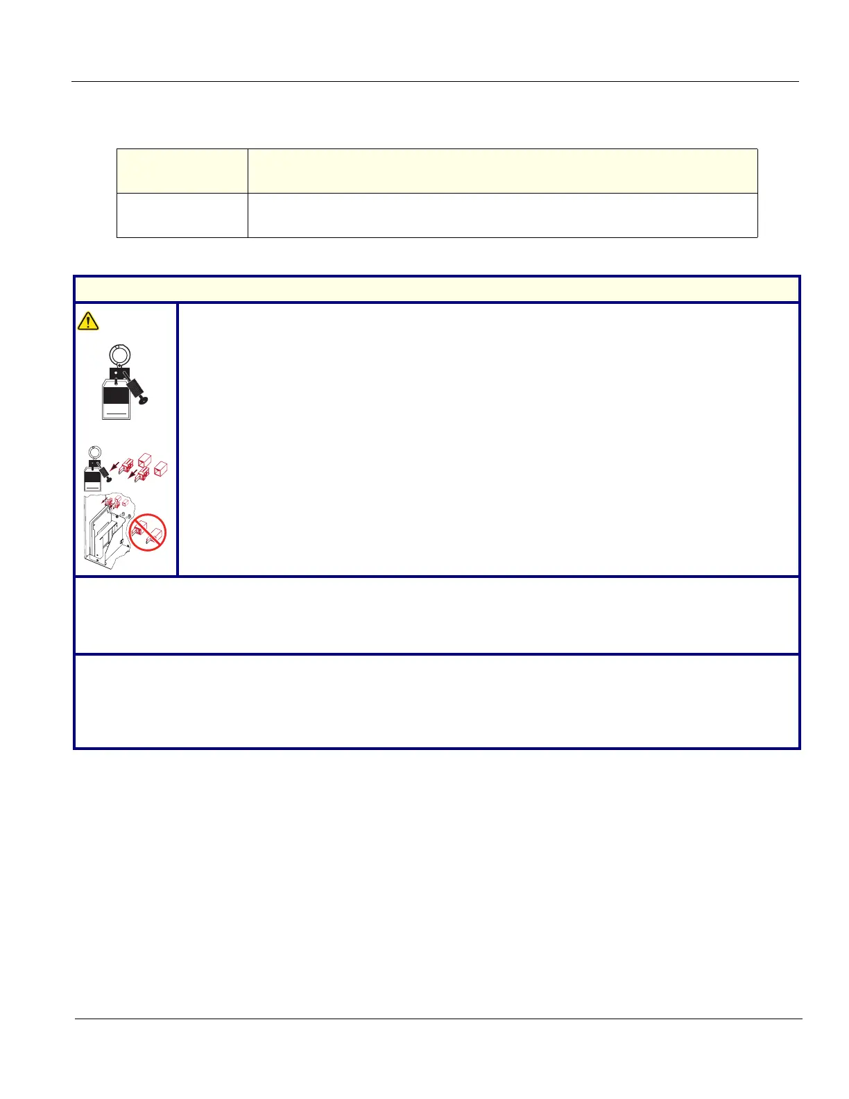
WARNINGWARNING
Energy Control and Power Lockout for LOGIQ E10:
When servicing parts of the Ultrasound System where there is exposure to voltage greater than 30
Volts:
1. TURN OFF THE SCANNER.
2. UNPLUG THE SYSTEM.
3. MAINTAIN CONTROL OF THE SYSTEM POWER PLUG.
4. WAIT FOR AT LEAST 20 SECONDS FOR CAPACITORS TO DISCHARGE AND THE ON/OFF
BUTTON (WHITE LIGHT ON THE OP PANEL) TO TURN OFF, AS THERE ARE NO TEST POINTS
TO VERIFY ISOLATION.
5. REMOVE THE BATTERY COVER AND DISCONNECT THE POWER CABLES J10 and J11 (black
and red) FROM THE BACKPLANE. See: 8-2-2 "Warnings" on page 8-3 and 8-11-15 "Rear I/O
replacement" on page 8-327.
Beware that the Main Power Supply, the Batteries, Power Module, ECB Shear Wave Capacitor Pack
may be energized, even if the power is turned OFF if the cord is still plugged into the AC Outlet.
1. Power down the system.
2. Disconnect the mains power cable from the wall outlet and all Probes and External I/O Cabling.
NOTE: If you are also replacing the Main Monitor, you do not need to remove the monitor from the arm.
3. Remove the Left Side Cover
, the Battery Cover, the Main Monitor assembly and the Bulkhead Cover.
Preparation Links (if you need more information):
• 4-2-4 "Power SHUT DOWN" on page 4-9.
• 8-6-3 "Side Cover(s)/Side Air Intake (Filter) inspection / replacement" on page 8-33.
• 8-7-2 "Main Monitor assembly replacement" on page 8-84.
• 8-6-18 "Bulkhead Cover replacement" on page 8-79.
Signed
Date
TAG
&
LOCKOUT
J10
J11
J10
J11
Sig n e d
Date
TAG
&
LOCKOUT