DIRECTION 5750007-1EN, REV. 1 LOGIQ E10 BASIC SERVICE MANUAL
8 - 254 Section 8-11 - Front End Acquisition / Card Cage parts replacement
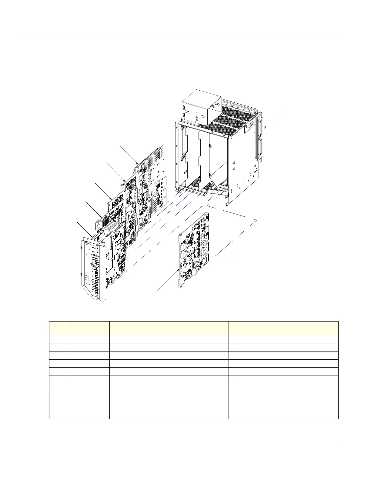
8-11-2 Front End Card Rack parts overview
Positions of the cards in a LOGIQ E10. Table 8-274 shows the positions of the cards. Position #1 is
nearest the Probe connectors (GRLY, front of Ultrasound System).
Figure 8-8 Front End Card Rack
NOTE: Torque all M6 screws and flange nuts in the Card Cage to 1.5 Nm (1.1 lbf-ft) unless otherwise specified.
Table 8-274 Card Cage Card Positions
Item ABBREVATION CARD NAME
TOTAL NUMBER OF CARDS PER
LOGIQ E10
1. GRLY
Relay Board
1
2. ETX 64
Transmitter Board
1
3. ETX 128
Transmitter Board
1
4. CRX2
Receive Board
1
5. ECB
LOGIQ E10 Carrier Board
1
6. EPM
Power Module
1
7. BP
Backplane
1
N/A
Front Plane /XD
BUS
The Front Plane Boards connect to the back of
the Relay Board, the Analog Receiver Boards and
the Transmitter Board. The Front Plane boards
are interchangeable.
2
5
6
1
2
3
4
7