DIRECTION 5750007-1EN, REV. 1 LOGIQ E10 BASIC SERVICE MANUAL
8 - 118 Section 8-7 - Replacing Top Console Parts
Upper OP/Touch Panel Assembly removal
Table 8-137 Upper OP/Touch Panel Assembly removal
Steps Corresponding Graphic
1. Make sure the Upper OP is in its uppermost position, with the Main Monitor out of the way.
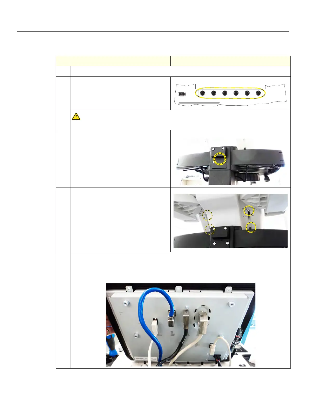
2. Remove the six Upper OP Encoder Knobs.
NOTICE
Failure to remove the six Upper OP Knobs first, could cause damage to the knob shafts.
3. At the rear of the Ultrasound System,
release the XY-Mech (frogleg) by inserting
a 1.5 mm (1/16 inch) hex wrench, straight
into the release point and pressing until
released.
Pull the console out to its extended position
to gain access to the Upper OP screws.
XY-Mech release
4. Remove the four screws and washers
securing the Upper OP from the rear of the
Upper UI Frame, using a #2 Phillips
screwdriver.
5. NOTE: MAKE SURE the six OP Knobs have been removed.
Swing the Main Monitor to the side.
Tilt the top toward the front of the Ultrasound System and disconnect the cables at the back of
the OP.