DIRECTION 5750007-1EN, REV. 1 LOGIQ E10 BASIC SERVICE MANUAL
8 - 120 Section 8-7 - Replacing Top Console Parts
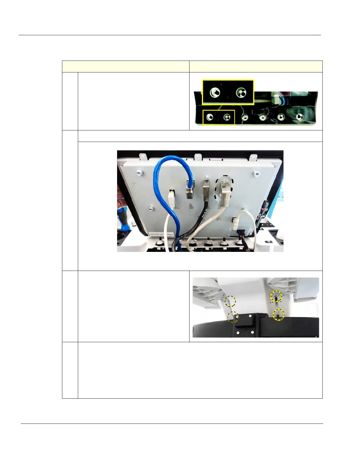
Upper OP/Touch Panel Assembly installation
Table 8-138 Upper OP/Touch Panel Assembly installation
Steps Corresponding Graphic
1. Position the Upper OP to the Upper UI
Frame, with the six Encoder holes centered
around the Encoders and tilted forward.
2. Connect the cables to the Upper OP.
Upper OP cables connected, see Figure 8-2 "Upper OP/Touch Panel assembly
cable placement" on page 8-119.
3. Slide the OP upward and re-install the four
screws and washers to secure the OP to
the Upper UI Frame. Torque 0.7 Nm
(0.52 lbf-ft).
4. The Knobs are keyed, notice that the joystick has a flat side to match the Knobs.
Re-install the six OP Knobs removed.
Before continuing, test the Encoders and Op Panel controls to ensure they operate properly. If
the Encoder seals are too close to the Encoder, the seals can cause the Encoder operation to
bind. If the seals are to high, the can limit the joystick operation. If the joystick operation is limited,
remove the Knob and gently press the seal(s) in.
Re-install the six OP Knobs and all Covers removed.