DIRECTION 5750007-1EN, REV. 1 LOGIQ E10 BASIC SERVICE MANUAL
8 - 158 Section 8-7 - Replacing Top Console Parts
Lower OP Frame installation
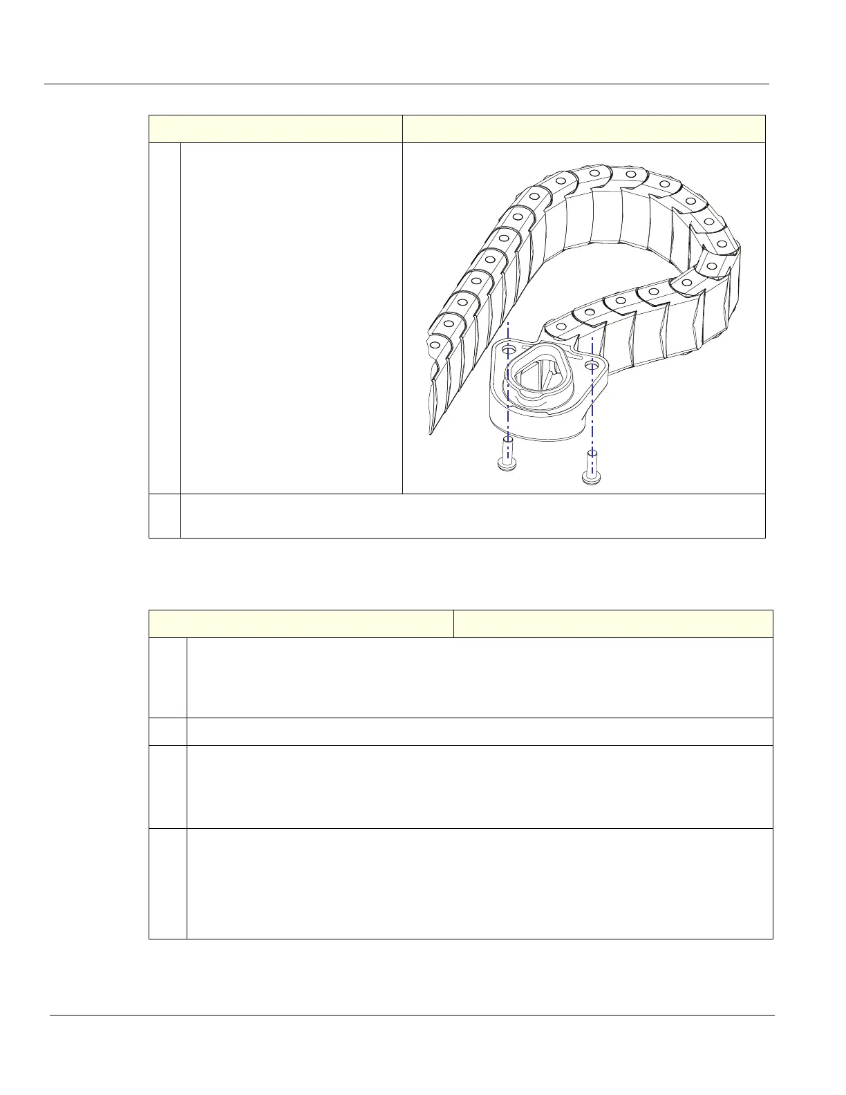
4. From underneath the Lower Frame,
remove the two screws securing the
Main Cable Assembly to the Lower
UI Frame, using a #2 Phillips screw
driver.
Pull the Main Cables through the
Frame opening to free the Frame.
5. Remove the two screws temporarily installed to hold the Lower UI Frame, while supporting the
Lower UI Frame and remove the Frame.
Table 8-183 Lower OP Frame installation
Steps Corresponding Graphic
1. Position the Lower UI Frame and temporally install two screws to hold the Lower UI Frame when
attaching the Main Cable Assembly.
Feed the cables into the Lower UI Frame and re-install the two screws to secure the Main Cable
Assembly to the Lower Frame.
2. Re-install the Upper Frame.
3. Support the two frames and remove the temporary screws.
Continue to support the Frames to install the Bulkhead Plate.
Re-install the Bulkhead Bracket Housing (behind the Bulkhead Plate) and install the Plate with
the five screws removed. The upper two screws are shorter.
4. Install the:
• Main Cable to the Lower OP,
• Bulkhead Board,
• Lower OP and Upper OP,
• Monitor Adapter, Monitor Arm and Monitor,
• re-install all Covers removed.
Table 8-182 Lower OP Frame removal
Steps Corresponding Graphic