DIRECTION 5750007-1EN, REV. 1 LOGIQ E10 BASIC SERVICE MANUAL
8 - 164 Section 8-7 - Replacing Top Console Parts
Left Handle Cover removal / installation
Table 8-191 Left Handle Cover removal
Steps Corresponding Graphic
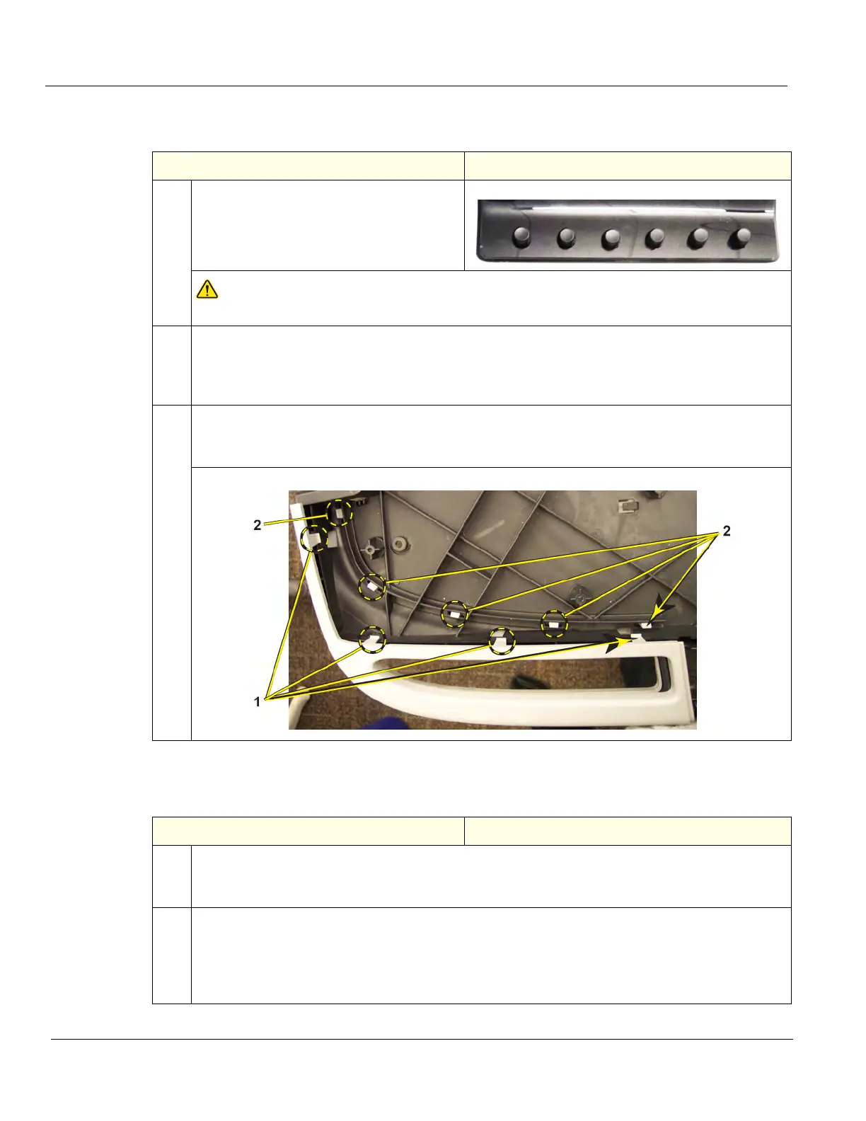
1. Remove the six OP Knobs.
NOTICE
Failure to remove the six OP Knobs first, could cause damage to the knob shafts.
2. Remove the:
• Upper OP,
• Lower OP,
• Palm Rest.
3. Release the:
• lock mechanisms (1) from the top Left Handle Cover,
• lock mechanisms (2) from the bottom Left Handle Cover.
Table 8-192 Left Handle Cover installation
Steps Corresponding Graphic
1. Position:
• bottom Left Handle Cover and secure with locking mechanisms.
• top Left Handle Cover and secure with locking mechanisms.
2. Re-install:
• Palm Rest.
• Lower OP.
• Upper OP,
• all Covers removed.