DIRECTION 5750007-1EN, REV. 1 LOGIQ E10 BASIC SERVICE MANUAL
8 - 264 Section 8-11 - Front End Acquisition / Card Cage parts replacement
Relay Board removal
Relay Board installation
Table 8-287 Relay Board removal
Step Corresponding Graphic
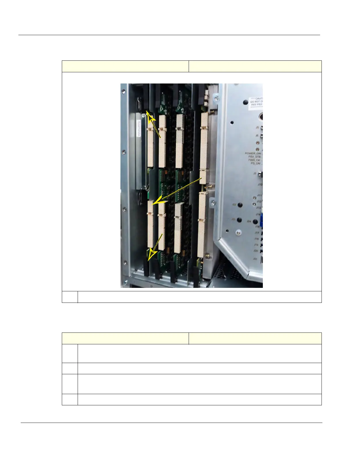
Relay Board location
1.
Using the board ejector levers, remove the Relay Board. Place it on an ESD safe place.
Table 8-288 Relay Board installation
Steps Corresponding Graphic
1. Carefully align the Relay Board with the rails and push it in until starts to seat in the Backplane
connectors and close the board ejector levers.
2. Carefully install the two Front Plane Boards.
3. Install the Card Rack Cover and fasten it with the fixing screws.
Connect the Hi-Pass cable to the GRLY and re-install the cover, if present.
4. Re-install all Covers removed.