DIRECTION 5750007-1EN, REV. 1 LOGIQ E10 BASIC SERVICE MANUAL
Chapter 8 Replacement Procedures 8 - 435
V Nav Option removal
For location of the Option in the LOGIQ E10, see: Table 8-401 "LOGIQ E10 Option Location" on page
8-408.
V Nav Option installation
Table 8-433 V Nav Option removal
Steps Corresponding Graphic
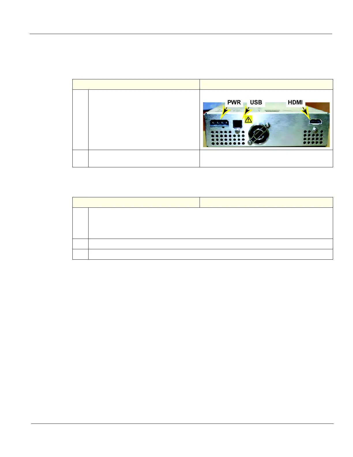
1.
Disconnect the cables to the rear of the
V Nav module.
2.
Remove the four screws securing the right
side of the V Nav module.
Table 8-434 V Nav Option installation
Steps Corresponding Graphic
1.
Re-connect cables to the rear of the V Nav module:
• HDMI from V Nav (GRLY Board).
• USB from J7 on the ECB I/O panel.
• PWR from J4 on the ECB I/O panel.
2.
Re-install the four screws to secure the right side of the V Nav module.
3.
Re-install all Covers removed.