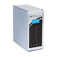
The front panel of the Reason H49 switch contains the following items:
Item Description
A
Liquid crystal display (LCD) with 4 lines of 16 characters:
Line 1: Empty
Line 2: H49
Line 3: IP address (255.255.255.255)
Line 4: Empty
B Navigation buttons to access and browse the device menu
Reason H49 is configured through the web application user interface (detailed later in
this document) or using configuration file.
Signification of the LEDs
Light Emitting Diodes (LEDs) and alarm contacts indicate the status of the product
and its ports:
LED
rank
Signification Color Description Activity
1
Power
1 LED
Green Powered on
Off Switch is off
2
Operating state
Amber
(default)
As long as the CPU board has not
booted.
Green
Healthy (board works, no contact
alarm)
3
Time
Synchronization
1 LED
Green PTP or NTP synchronization
Red
No synchronization or Switch in
Grandmaster
4 to 9
Port activity
6 LEDs
Green 1Gbits/s
Amber 100Mbits/s
Red
Not forwarding (access violation,
wrong MAC address)
No traffic On
Signs of activity Blinking
Not plugged or disabled by
configuration
Off
18
Alarm
1 LED
Red (default)
Power redundancy alarm
19
HSR RedBox
1 LED
Green
20
PRP RedBox
1 LED
Green
21
PRP-HSR Coupling
1 LED
Green
22
HSR QuadBox
1 LED
Green