5-22 Series 90-30 PLC Installation and Hardware Manual
–
August 2002 GFK-0356Q
5
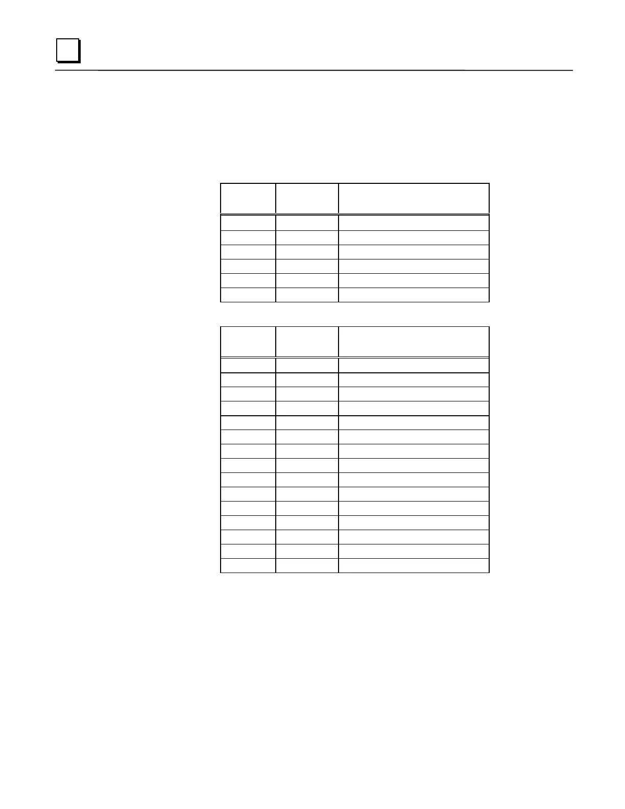
Pin Assignments for CPU351, CPU352, and CPU363 Serial Ports 1 & 2
The following two tables describe the pin assignments for each of the two front panel serial ports
on the CPU351, CPU352, and CPU363.
Table 5-6. Port 1 (RS-232)
Pin
Number
Signal
Name Description
1 CTS Clear To Send
2 TXD Transmit Data
3 0V Signal Ground
4 0V Signal Ground
5 RXD Receive Data
6 RTS Request to Send
Table 5-7. Port 2 (RS-485)
Pin
Number
Signal
Name Description
1 Shield Cable Shield
2 NC No Connection
3 NC No Connection
4 NC No Connection
5+5VDCLogic Power *
6 RTS(A) Differential Request to Send
7 SG Signal Ground
8 CTS(B‘) Differential Clear To Send
9 RT Resistor Termination
10 RD(A‘) Differential Receive Data
11 RD(B‘) Differential Receive Data
12 SD(A) Differential Send Data
13 SD(B) Differential Send Data
14 RTS(B’) Differential Request To Send
15 CTS(A’) Differential Clear To Send
* Note that Pin 5 provides Isolated +5 VDC power (100 mA maximum) for
powering external options.
 Loading...


