A-8 Series 90-30 PLC Installation and Hardware Manual
–
August 2002 GFK-0356Q
A
Serial Cable Diagrams
This section describes only a few of the many and various Point-to-Point, and Multidrop serial port
connections for Series 90 PLCs.
In the point-to-point configuration only two devices can be connected to the same communication
line. The communication line can be directly connected using RS-232 (50 feet, 15 meters
maximum) or RS-485 (4000 feet, 1200 meters maximum). Modems can be used for longer
distances.
Note
The cable connector for the Series 90-70 and Series 90-30 PLCs serial port must
be a right angle connector in order for the hinged door on the module to close
properly. Refer to Table A-1 Connector/Cable Specification.
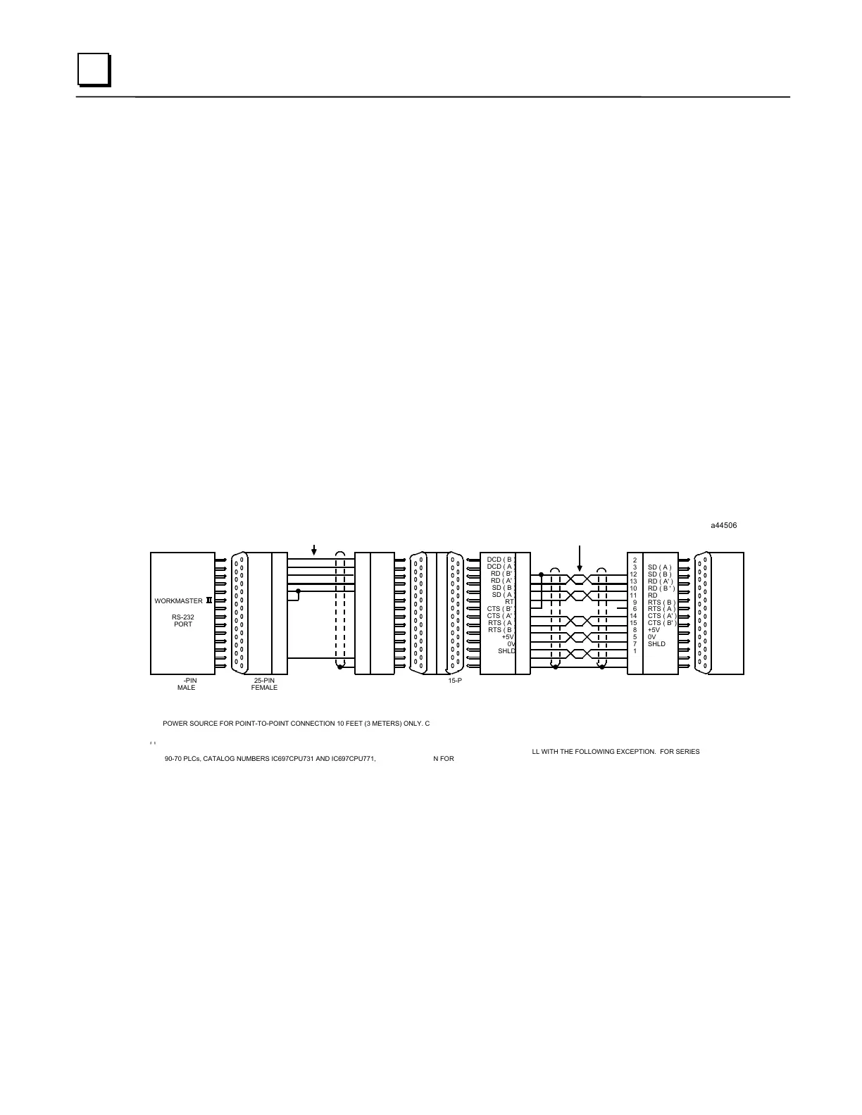
RS-232 Point-to-Point Connections
The next three figures illustrate typical RS-232 point-to-point connection to Series 90 PLCs.
2
3
10
11
12
13
9
15
8
6
14
5
7
1
a44506
15-PIN
FEMALE
RS-485
PORT
RS-232/RS-485
CONVERTER
(IC690ACC900)
25-PIN
FEMALE
RS-232
PORT
RD
TD
CTS
RTS
DCD
GND
SHLD
3
2
5
4
8
7
1
PIN
25-PIN
MALE
PIN
TD
RD
RTS
CTS
DCD
DTR
GND
IC690CBL705 OR EQUIVALENT
RS-232
SHIELDED PAIRS
2
3
4
5
8
20
7
25-PIN
MALE
25-PIN
FEMALE
RS-232
PORT
WORKMASTER
**
2
3
12
13
10
11
9
6
14
15
8
5
7
1
SD ( A )
SD ( B )
RD ( A' )
RD ( B ' )
RD
RTS ( B )
RTS ( A )
CTS ( A' )
CTS ( B' )
+5V
0V
SHLD
DCD ( B )
DCD ( A )
RD ( B' )
RD ( A' )
SD ( B )
SD ( A )
RT
CTS ( B' )
CTS ( A' )
RTS ( A )
RTS ( B )
+5V
0V
SHLD
POWER SOURCE FOR POINT-TO-POINT CONNECTION 10 FEET (3 METERS) ONLY. CONVERTER POWER SOURCE BEYOND 10 FEET (3 METERS) AND FOR MULTIDROP
CONNECTION MUST BE EXTERNAL SOURCE.
*
PIN
PIN
15- PIN
MALE
15- PIN
MALE
15- PIN
FEMALE
SERIES
90 PLC
RS-422
PORT
RS-422
TWISTED SHIELDED
PAIRS
*
*
**
TERMINATION RESISTANCE FOR THE RECEIVE DATA (RD) SIGNAL NEEDS TO BE CONNECTED ONLY ON UNITS AT THE END OF THE LINES. THIS TERMINATION IS MADE ON
THE SERIES 90 PLC PRODUCTS BY CONNECTING A JUMPER BETWEEN PIN 9 AND PIN 10 INSIDE THE 15-PIN D-SHELL WITH THE FOLLOWING EXCEPTION. FOR SERIES
90-70 PLCs, CATALOG NUMBERS IC697CPU731 AND IC697CPU771, THE TERMINATION FOR RD AT THE PLC IS IMPLEMENTED BY A JUMPER BETWEEN PIN 9 AND PIN 11.
 Loading...


