EasyManuals Logo

GE Series 90-30 PLC User Manual

GE Series 90-30 PLC
445 pages
To Next Page IconTo Next Page
To Previous Page IconTo Previous Page
Page #405 background imageLoading...
Page #405 background image
H-4 Series 90-30 PLC Installation and Hardware Manual
August 2002 GFK-0356Q
H
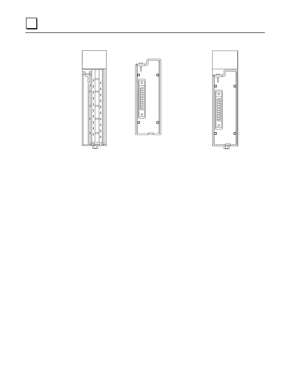
Step 3: Snap I/O Face Plate assembly on module
Step 4: Connect cable to connector on terminal block
Finally, connect the selected length cable from the connector on the I/O Face Plate to the connector
on the interposing terminal block.
Module Wiring Information
Refer to GFK-0898,
Series 90-30 PLC I/O Module Specifications Manual
for wiring connections
for each module.
Cable Information
Data sheets for the cables are found in the “Cables” chapter of this manual.
A1 2 3 4 5 6 7 8
B1 2 3 4 5 6 7 8
F
A1 2 3 4 5 6 7 8
B1 2 3 4 5 6 7 8
F
Installing the I/O Face Plate
Module with I/O Face Plate Installed
a47118

Table of Contents

Questions and Answers:

Question and Answer IconNeed help?

Do you have a question about the GE Series 90-30 PLC and is the answer not in the manual?

GE Series 90-30 PLC Specifications

General IconGeneral
Series90-30
TypeProgrammable Logic Controller (PLC)
Relative Humidity5% to 95% non-condensing
ManufacturerGE Fanuc (now part of Emerson)
MemoryVaries by CPU model
Power SupplyVarious options (e.g., 120/240V AC, 24V DC)
I/O ModulesDigital, Analog, Specialty modules
I/O CapacityUp to 512 I/O points
Communication PortsRS-232, RS-485, Ethernet
Programming SoftwareProficy Machine Edition
Programming LanguagesLadder Logic, Instruction List
Operating Temperature0°C to 60°C (32°F to 140°F)
CertificationsUL, CE

Related product manuals