GFK-0356Q Appendix B IC690ACC900 Converter B-7
B
Jumper Configuration
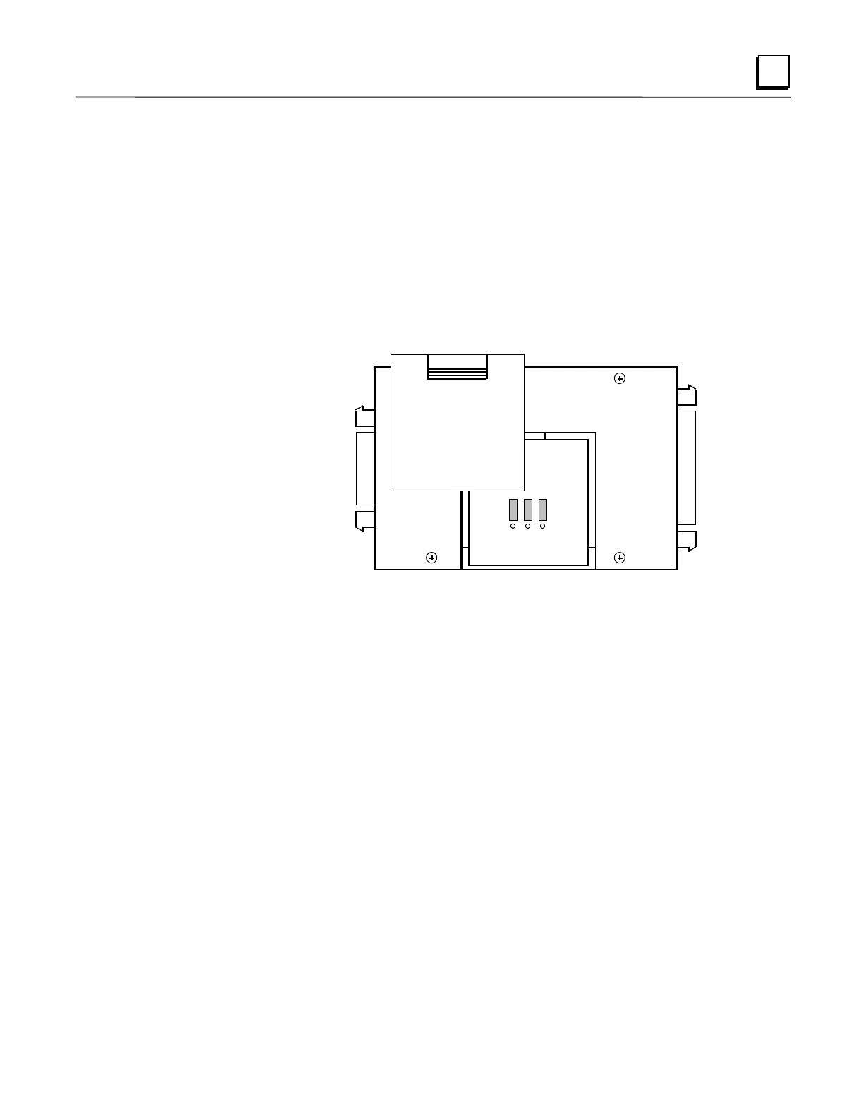
There are three jumper locations on the converter board for selection of user options. Each jumper
position has three pins, as shown in the following illustration. These jumper positions, labeled JP2,
JP3, and JP4, are accessed by removing the square plastic cover on the top of the converter.
Configuration can be changed as required by carefully removing one or more of the jumpers with a
pair of needle nose pliers and placing it on the desired pair of pins.
Refer to the description of these selectable jumper positions in the following table and place the
jumper on the selected pair of pins. The pin numbers are 1, 2, and 3. Default jumper locations are
indicated by a rectangle around the pins to be jumpered for each position. The default pin numbers
are 1 and 2.
1
2
3
RS-422/RS485
RS-232
Figure B-5. Location of Jumpers for User Options
 Loading...


