8-42 Series 90-30 PLC Installation and Hardware Manual
–
August 2002 GFK-0356Q
8
Dimensions
PTMPM
Standard size Series 90-30 module, mounts in a Series 90-30 baseplate.
PTMIM
Interface module. Approximately 4.5” (114 mm) long by 3” (76 mm) wide. It is
mounted on a standard 35 mm DIN-rail.
IC693CBL340
Interface cable
Approximately 19” (0.5 Meter) long.
IC693CBL341
Interface cable
Approximately 39” (1 Meter) long.
PTMPM Indicator LEDs
F (Fault) - This RED LED, when OFF, indicates that there are no interface faults. When ON,
either steady or flashing, it indicates that one or more of three possible faults is present: (1)
Phase A input not present, (2) over-range condition on one or more inputs (voltage or current
values too high), and (3) phase polarity fault. Each of these three fault signals has a %I status
bit in the PLC.
R (Running) - This Green LED, when ON, indicates that the module is “running” (functioning
properly). When OFF, it indicates a module failure.
General Mounting Information
It is recommended the PTMPM modules be mounted in a slot at or near the end of the PLC and that
the PTMIM be mounted to the panel to the side of the PLC (the PTMIM mounts on a standard
DIN-rail). This will keep the power wiring to the PTMIM physically separated from PLC signal
wiring, thus reducing the opportunity for noise coupling. The PTMIM ground requirements
must be strictly adhered to - refer to the user’s manual, GFK-1734 for instructions. See
Warning note below.
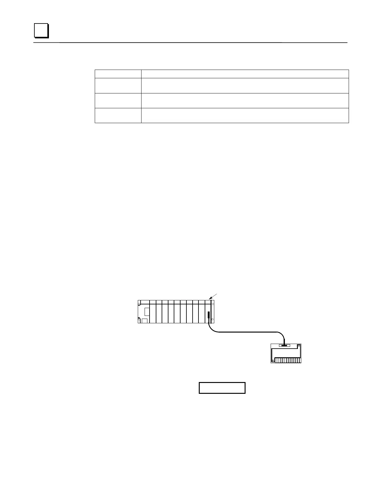
Series 90-30 PLC
PTMIM
PTM
IC693CBL340/341 PTM Cable
PTMPM
Figure 8-24. IC693PTM100/101 Component Mounting
Warning
The PTMIM board connects to hazardous voltages. Before installing,
testing, or troubleshooting this board, you should read the complete
instructions in the PTM User’s Manual, GFK-1734. Failure to follow the
guidelines in the PTM User’s Manual may result in personal injury,
equipment damage, or both.
 Loading...


