GFK-0356Q 13-1
Maintenance and Troubleshooting
Troubleshooting Features of Series 90-30 Hardware
Indicator Lights (LEDs) and Terminal Board
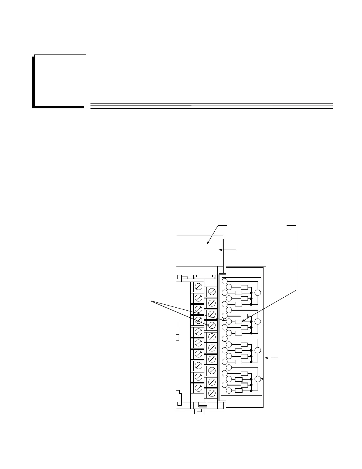
The following figure shows how the indicator LEDs correspond to the circuit connection points on
an I/O Module’s terminal board. The terminal board terminals are numbered from the top, with the
top terminal in the left row being number 1 and the top terminal in the right row being number 2.
The numbers alternate between rows with even numbers on the right and odd numbers on the left,
as shown in the circuit diagram on the back of the hinged cover.
A1
A2
A4
A3
A1 2 3 4 5 6 7 8
B1 2 3 4 5 6 7 8
F
RELAY
OUTPUT
2 AMP
1
2
3
V
V
V
V
5
6
7
8
9
10
11
12
13
14
15
16
17
18
19
20
4
A7
A8
B1
B2
B4
B7
B8
44A726782-015
FOR USE WITH
IC693MDL940
B6
B5
A1
A2
A3
A4
A5
A6
B3
Fuse Indicator LED
LED A6 corresponds to circuit A6:
ircuit A6 connects
o terminal 8
Hinged Cover
Indicates External
Power Supply
Figure 13-1. Relationship of Indicator Lights to Terminal Board Connections
13
Chapter
 Loading...


