GFK-0356Q Chapter 8 Option Modules 8-3
8
Status LEDs
The LEDs on the front of the GCM module indicate its operating status and should be on during
normal operation.
OK Shows the status of the GCM module. This LED turns on after power up diagnostics are
completed.
COM Shows the status of the Genius communications bus. This LED is on steadily when the bus
is operating properly. It blinks for intermittent bus errors and is off for a failed bus. It is
also off when no configuration has been received from the PLC CPU.
FIRST
DEVICE
SHIELD
OUT
SHIELD
IN
SERIAL
2
SERIAL
1
R
SHIELD
OUT
SHIELD
OUT
LAST
DEVICE
SHIELD
OUT
R
SHIELD
IN
SERIAL
2
SERIAL
1
SHIELD
IN
SERIAL
2
SERIAL
1
SHIELD
IN
SERIAL
2
SERIAL
1
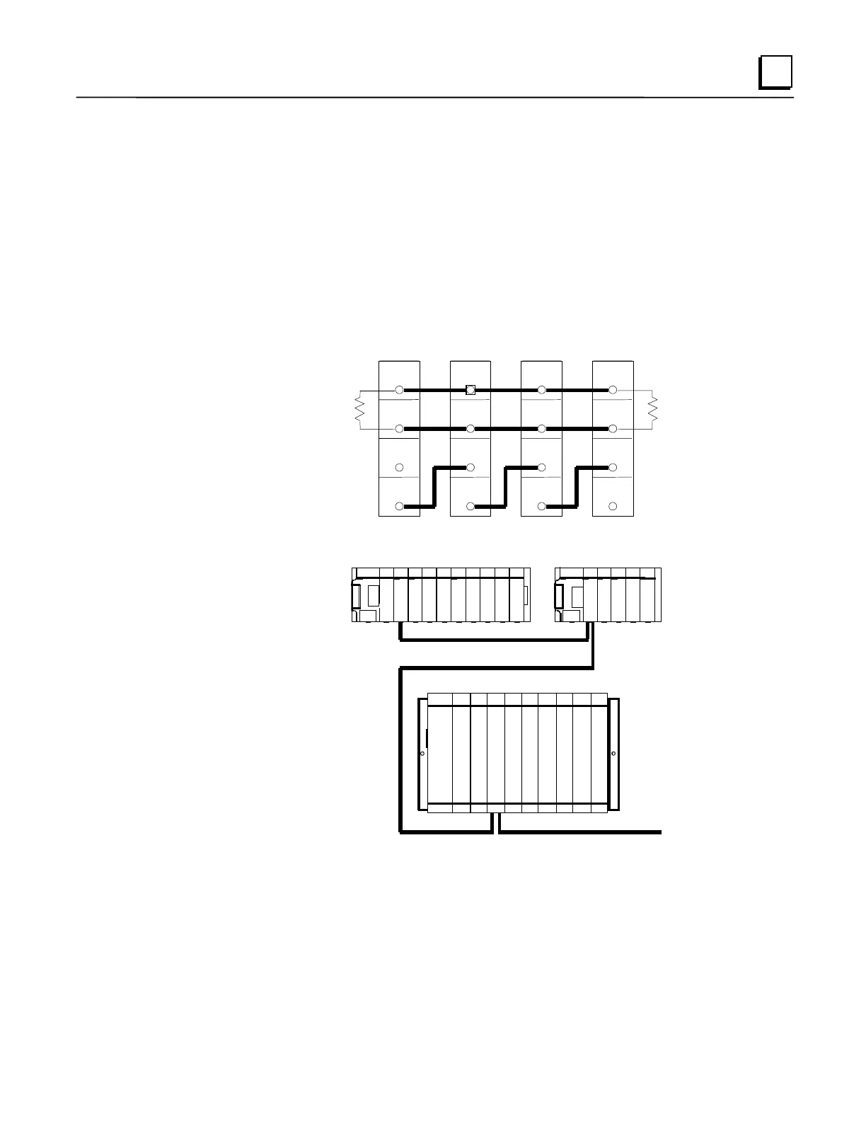
Figure 8-2. Genius Bus Wiring Schematic
SERIES 90-70
C
P
U
G
C
M
G
C
M
SERIES 90-30
SERIES 90-30
GENIUS COMMUNICATIONS BUS
B
G
C
Figure 8-3. Example of Genius Communications Network
GCM Documentation
For detailed information on the Genius Communications Module, including installation
instructions, refer to GFK-0412, the
Series 90-30 Genius Communications Module User’s Manual
.
 Loading...


