F-6 Series 90-30 PLC Installation and Hardware Manual
–
August 2002 GFK-0356Q
F
Step 5: Final Calculation
Once the individual power dissipations have been calculated, add them all to obtain total PLC heat
dissipation. Note that the PLC baseplate, analog input modules, and analog output modules have
been ignored in this procedure because their power dissipation values are negligible when
compared with the total. Also, since each Series 90-30 rack has its own power supply, each rack
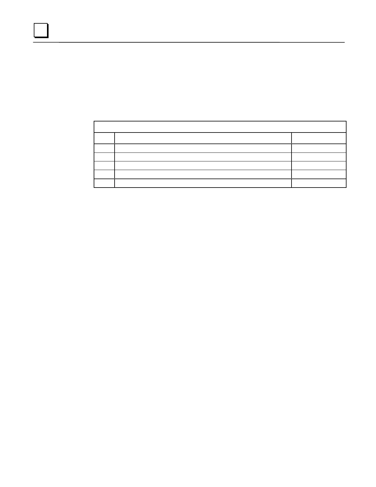
should be calculated on an individual basis. The following table summarizes the final calculation:
Series 90-30 Rack Heat Dissipation Calculation Summary
Step Description Value (Watts)
1 Calculate total of dissipation values for all modules in the rack
2 Divide value obtained in Step 1 by 2 to obtain Power Supply value
3 Calculate total of all Output modules’ output dissipation values
4 Calculate total of all Input modules’ input dissipation values
5 Add the above four values to obtain the total dissipation of the rack
Other Information Related to Enclosure Sizing
The “Baseplates” chapter of this manual contains rack dimensions and minimum ventilation
clearance distances required around the racks. The “Cables” chapter contains clearance dimensions
for cables that mount on the front of modules.
 Loading...


