IC655CCM590 Converter
GFK-0356Q Appendix C IC655CCM690 Isolated Repeater/Converter C-3
C
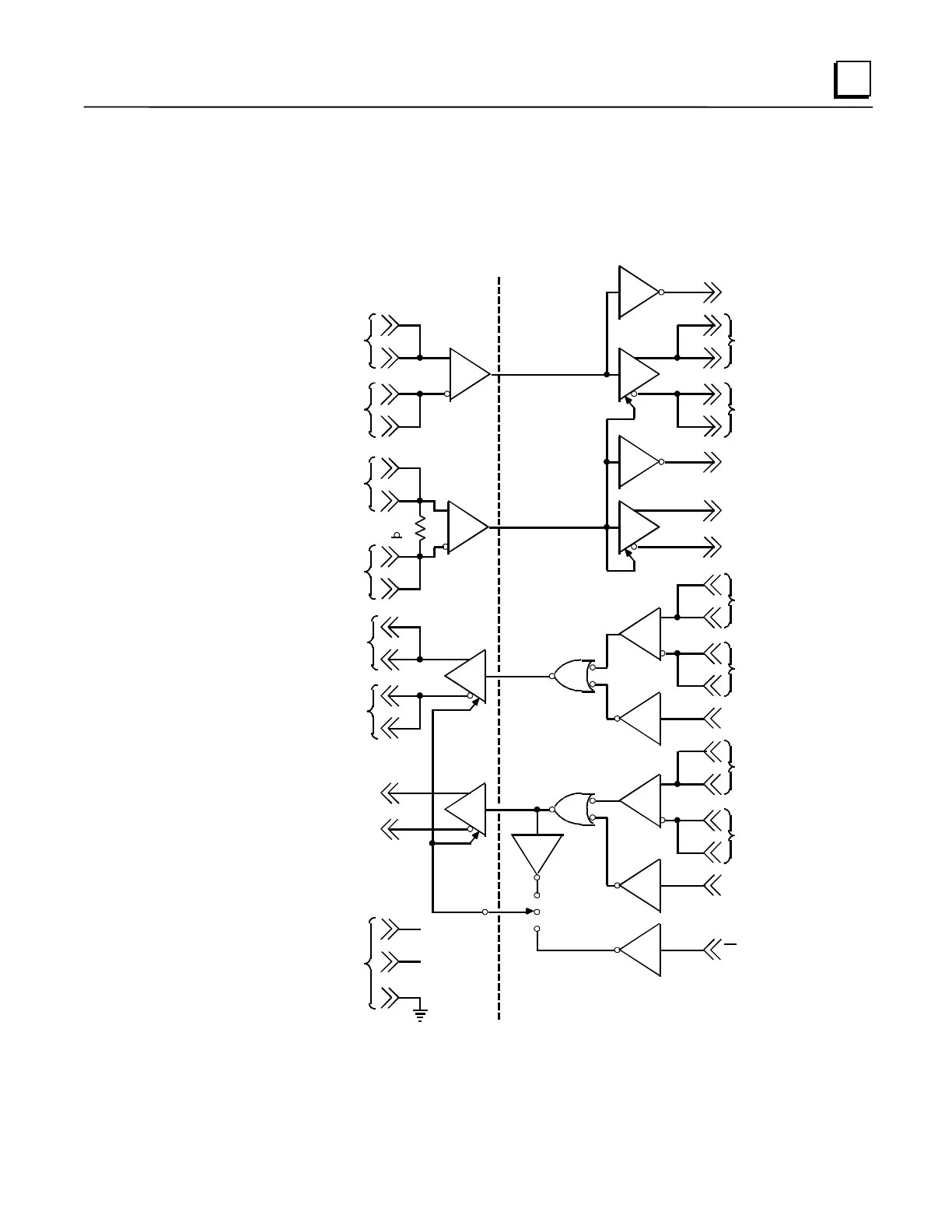
Logic Diagram of the Isolated Repeater/Converter
The figure below provides a functional look at the unit. Note the 3-position switch for controlling
the J1 port transmitters. This switch is discussed in
System Configurations
later in this appendix..
14
RS-422/RS-232C
J2
RS-422
J1
10
CTS ( B' )
8
15
22
23
RD ( B' )
RD ( A' )
11
9
CTS ( A' )
16
17
D ( B )
25
24
D ( A )
13
12
RTS (B )
RTS (A )
SD (RS-232C)
2
15
14
SD (B )
22
23
SD (A )
11
10
RTS (RS-232C)
RTS (B )
4
RTS (A )
18
16
17
RD ( B' )
19
RD ( A' )
3
RD (RS-232C)
9
13
12
CTS ( B' )
8
CTS ( A ')
5
CTS (RS-232C)
RESISTOR
150
25
SE (RS-232C)
( CTS)
(ON)
(SE)
115
VAC
OPTICAL
ISOLATION
ISOLATED
POWER
SUPPLIES
Figure C-2. RS-422 Isolated Repeater/RS-232 Converter Logic Diagram
Note: All inputs are biased to the inactive state. Inputs left unconnected will produce a binary 1
(OFF) state on the corresponding output.
 Loading...


