E-2 Series 90-30 PLC Installation and Hardware Manual
–
August 2002 GFK-0356Q
E
Connectors
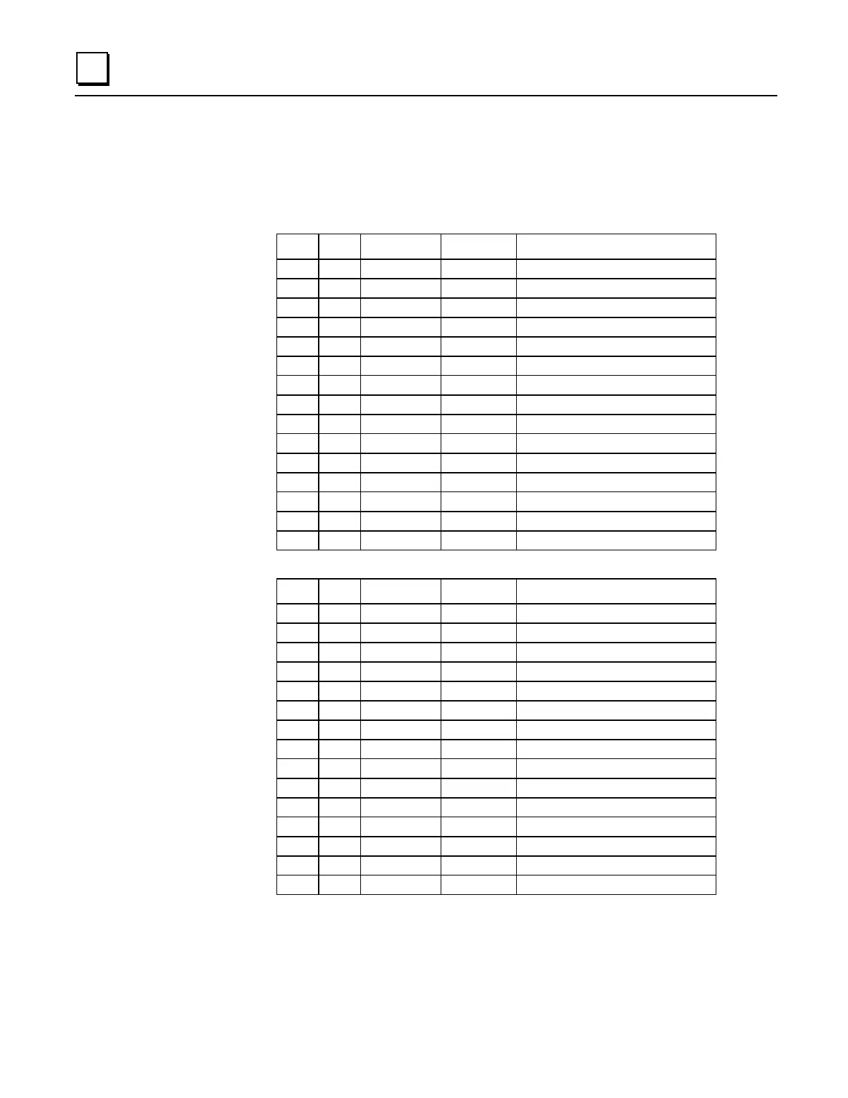
The Isolator provides two connectors, one 15 pin male D-type (PL1) and one
15 pin female D-type (PL2).
RS-485 Connectors
Pin Pin Name Pin Type Description
PL1
1
SHLD
-
Chassis Ground
2
NC
-
3
NC
-
4
NC
-
5
5V
-
+5V power
6
CTS (A')
In
Clear to send -
7
0V
-
Signal Ground
8
RTS (B)
Out
Request to send +
9
NC
-
10
SD (A)
Out
Send data -
11
SD (B)
Out
Send data +
12
RD (A')
In
Read data -
13
RD (B')
In
Read data +
14
CTS (B')
In
Clear to send +
15
RTS (A)
Out
Request to send -
Pin Pin Name Pin Type Description
PL2
1
NC
-
2
NC
-
3
NC
-
4
NC
-
5
5V
-
+5V power
6
RTS (A)
Out
Request to send -
7
0V
-
Signal Ground
8
CTS (B')
In
Clear to send +
9
RT
-
Terminating Resistor*
10
RD (A')
In
Read data -
11
RD (B')
In
Read data +
12
SD (A)
Out
Send data -
13
SD (B)
Out
Send data +
14
RTS (B)
Out
Request to send +
15
CTS (A')
In
Clear to send -
* Use the terminating resistor if the Port Isolator is used in port-to-port mode or at the end of a multi-drop
configuration. To terminate the RD balanced line, place a jumper wire from pin 9 to pin 10.
* A denotes – and B denotes +. A and B denote outputs and A' and B' denote inputs.
 Loading...


