9-12 Series 90-30 PLC Installation and Hardware Manual
–
August 2002 GFK-0356Q
9
module configuration at power-up and periodically throughout the operation. The actual
configuration must match the programmed configuration. Any detected deviations are reported to
the CPU alarm processor function for the configured fault response. Refer to GFK-1056, the
Series
90-30 State Logic CPU User’s Manual
for more information.
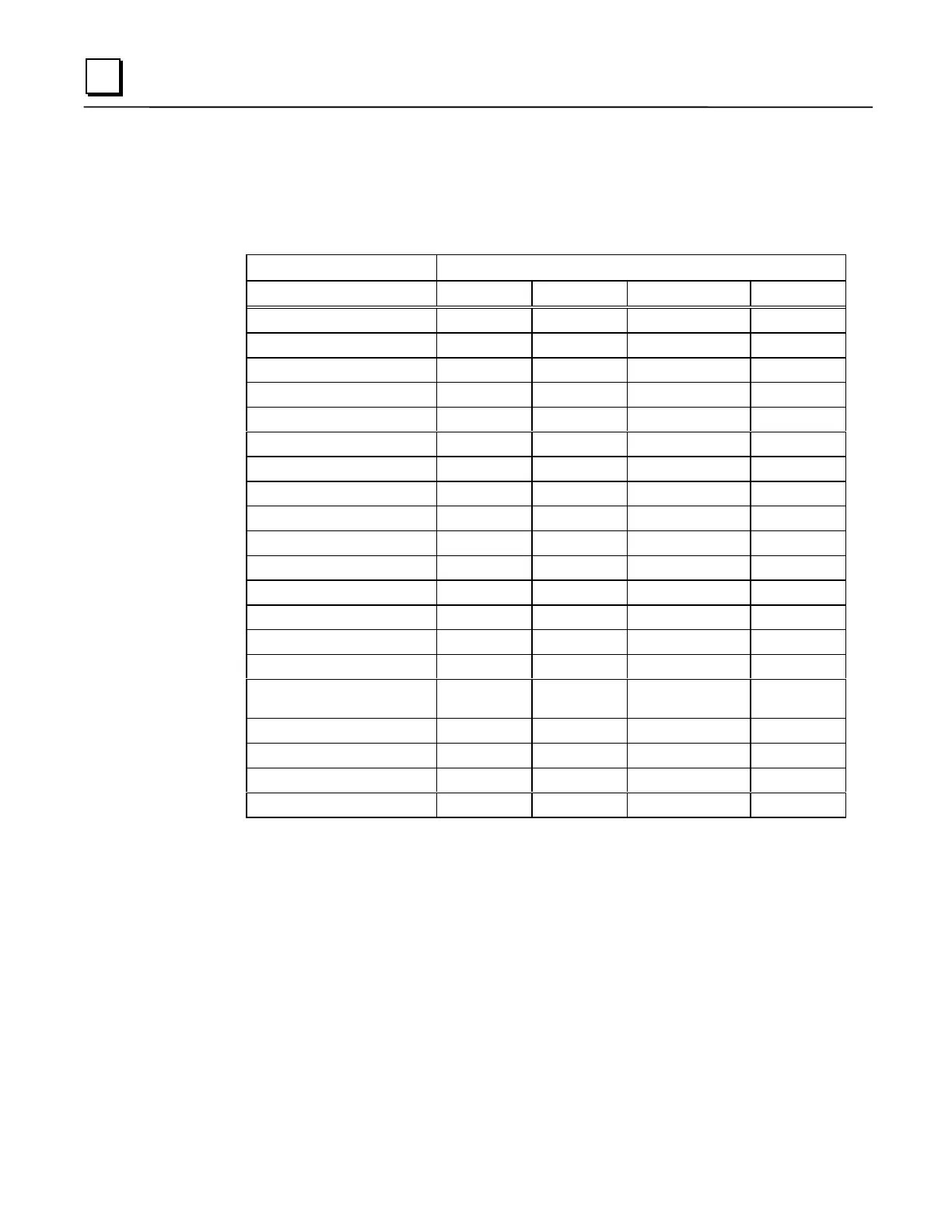
Table 9-1. System Specifications for Series 90-30 State Logic CPUs
State Logic CPU Model
CSE 340 CSE 331 CSE 313/323 CSE 311
Digital Inputs, %I
1024 1024 512512
Digital Outputs, %Q
1024 1024 512512
Global I/O, %G
1280 1280 1280 1280
Internal Flags
1000 1000 500 500
Analog Inputs, %AI
256 256 128 128
Analog Outputs, %AQ
128 128 64 64
PID Loops
20 20 20 20
Integer Variables
1000 1000 250 250
Floating Point Variables
250 250 61 61
String Variables
20 20 8 8
Character Variables
64 64 64 64
Tables
20 20 10 10
Program Memory
98K Bytes 48K Bytes 20K Bytes 10K Bytes
Processor Speed
20 MHz 10 MHz 10 MHz 10 MHz
Number of Baseplates
5511
Baseplate Size
5 or 10 slots 5 or 10 slots 5 slots (CSE313)
10 slots (CSE323)
5 slots
Supports SCM
Yes Yes No No
Serial Ports
111 1
Clock/Calendar
Hardware Hardware Software Software
Table Memory Space
4K Bytes 4K Bytes 1K Bytes 1K Bytes
For more detailed information on State Logic CPU specifications, see GFK-1056, the
Series 90-30
State Logic Control System User’s Manual
.
 Loading...


