Reference Manual Preliminary
Prox–DU & Prox–SU
www.gemalto.com Release for first samples Do not use for final design
DOC118569A Public Use Page 10/134
Table 37 – USB Contactless Smart Card Device Class Descriptor.................................... 103
Table 38 – USB Contactless Smart Card Interface Endpoint Descriptor (Bulk Out) .......... 103
Table 39 – USB Contactless Smart Card Interface Endpoint Descriptor (Bulk In) ............. 103
Table 40 – USB Contactless Smart Card Interface Endpoint Descriptor (Interrupt In)....... 103
Table 41 – USB Contact Smart Card Device Class Descriptor .......................................... 105
Table 42 – USB Contact Smart Card Interface Endpoint Descriptor (Bulk Out)................. 105
Table 43 – USB Contact Smart Card Interface Endpoint Descriptor (Bulk In).................... 105
Table 44 – USB Contact Smart Card Interface Endpoint Descriptor (Interrupt In) ............. 106
Table 45 – USB LangID String Descriptor .......................................................................... 106
Table 46 – USB Manufacturer String Descriptor................................................................. 106
Table 47 – USB Product String Descriptor.......................................................................... 107
Table 48 – USB Serial Number String Descriptor............................................................... 107
Table 49 – USB HID Interface String Descriptor................................................................. 108
Table 50 – USB Contactless Smart Card Interface String Descriptor................................. 109
Table 51 – USB Contact Smart Card Interface String Descriptor....................................... 109
Table 52 - Boot-loader HID error codes .............................................................................. 113
Table 53 – USB Boot-loader Configuration Descriptor ....................................................... 114
Table 54 – USB Boot-loader Interface String Descriptor .................................................... 116
Table 55 : LEDs states for the Boot-loader LEDs ............................................................... 116
Table 56 – Memory Sectors of MIFARE
®
1K....................................................................... 121
Table 57 – Memory Sectors of MIFARE
®
4K....................................................................... 123
Table 58 – Memory mapping of MIFARE
®
UL .................................................................... 124
Table 59 - Access to Data Blocks ....................................................................................... 132
Table 60 - Access to Sector Trailer..................................................................................... 133
FIGURE LIST
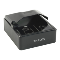
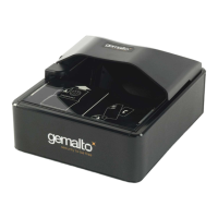
Figure 1 – Prox–DU view ...................................................................................................... 13
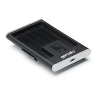
Figure 2 – Prox–SU view....................................................................................................... 13
Figure 3 - Prox–DU with the stand for vertical use ............................................................... 14
Figure 4 - Prox–DU ID-1 size slot ......................................................................................... 15
Figure 5 - Prox–SU ID-000 size slot...................................................................................... 15
Figure 6 – Dual interface smart card view............................................................................. 16
Figure 7 – The contactless smart card is put near or over the Prox–DU landing zone ........ 17
Figure 8 – The contactless smart card is not fully inserted into the Prox–DU slot .............. 17
Figure 9 – The contactless smart card is fully inserted into the Prox–DU slot (after the
switch activation) .......................................................................................................... 17
Figure 10 – The contact smart card is fully inserted into the Prox–DU slot .......................... 18
Figure 11 – The contactless smart card is put near or over the Prox–SU landing zone....... 18
Figure 12 – The contact SIM/SAM card is inserted into the Prox–SU connector ................. 18
Figure 13 – USB devices (Windows XP example) ................................................................ 21
Figure 14 - Contactless logo of the landing zone.................................................................. 21
Figure 15 – Contact card slot (Prox–DU and Prox–SU) ....................................................... 22
Figure 16 – ID-1 and ID-000 card size .................................................................................. 22
Figure 17 – Visual indicators................................................................................................. 23
Figure 18 – Prox–DU Installation popup dialog boxes.......................................................... 27
Figure 19 – USB smart card reader icons in the Device Manager window (Windows XP) .. 29
Figure 20 – USB HID icons in the Device Manager window (Windows XP)......................... 29
Figure 21 – Contactless smart card check............................................................................ 29
Figure 22 – Contact smart card check .................................................................................. 30
Figure 23 – PC/SC Architecture............................................................................................ 37
Figure 24 – Gem_PCSC window .......................................................................................... 40
Figure 25 – Prox–DU PC/SC name ...................................................................................... 41
Figure 26 – Prox–SU PC/SC name....................................................................................... 41
Figure 27 – Prox–DU and Prox–SU PC/SC names .............................................................. 41
Figure 28 – Two Prox–DU PC/SC names............................................................................. 41