105
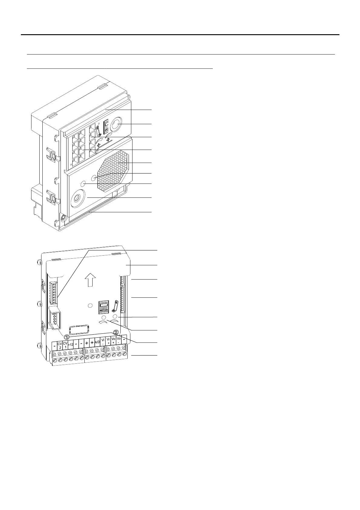
Microphone.
Front.
Sound module buttons (x2).
Connection block.
C 2N button connector.
Back.
: Negative
:
Contact “C” for electric lock. Relay 3.
: Contact “N.O.” for electric lock. Relay 3.
: Positive, negative.
: Audio and digital communication.
: Video signal input.
: Video signal output.
: Negative
Colour camera (Only the EL632 R5 module)P/T
CV1
CV2
+,
A/D
Vi+,Vi-
Vo+,Vo-
_
Telephone speaker volume control potentiometer.
LEDs (visual indications for people with impaired hearing)
C 7N NEXA Bus connector.
Description of the EL632 R5 - EL642/R5 sound module:P/T
Sw1 DIP switch.
Door panel speaker volume control potentiometer.
Button number.
DESCRIPTION OF THE SOUND MODULES
_
_
Speaker.
L .EDs (Only function with EL632 R5 P/T module).
Telephone speaker volume control potentiometer.
Door panel speaker volume control potentiometer.
AUDIO AND VIDEO DOOR ENTRY SYSTEM - CODED PANEL WITH DISPLAY

 Loading...