114
INSTALLATION OF THE DOOR PANEL
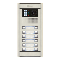
Fastening the frame to the embedding box:
Insert one end of the Nexa Bus link hose supplied with the product into the sound
module connector and the other end into either of the two connectors situated on
the bottom right of the N3403/AL display module. Connect the N3301/AL coded
module in the same way.
NOTE: Only the EL632 sound/EL642 Plus, EL632/EL642 R5 or EL632/Gtwin
module should be connected to the power supply unit. The N3301/AL
coded module receives power once it has been connected to the sound
module via the Nexa BUS link connector. See p. 1 1 for the wiring4 -142
diagrams.
Nexa Bus connection:
AUDIO AND VIDEO DOOR ENTRY SYSTEM - CODED PANEL WITH DISPLAY
IMPORTANT: For the location of the electronic modules in a Gtwin system, see page .101
*
( )
IMPORTANT: For the location of the electronic modules in a Gtwin system,
see page .101
*
( )
*
( )
*
( )
*
( )
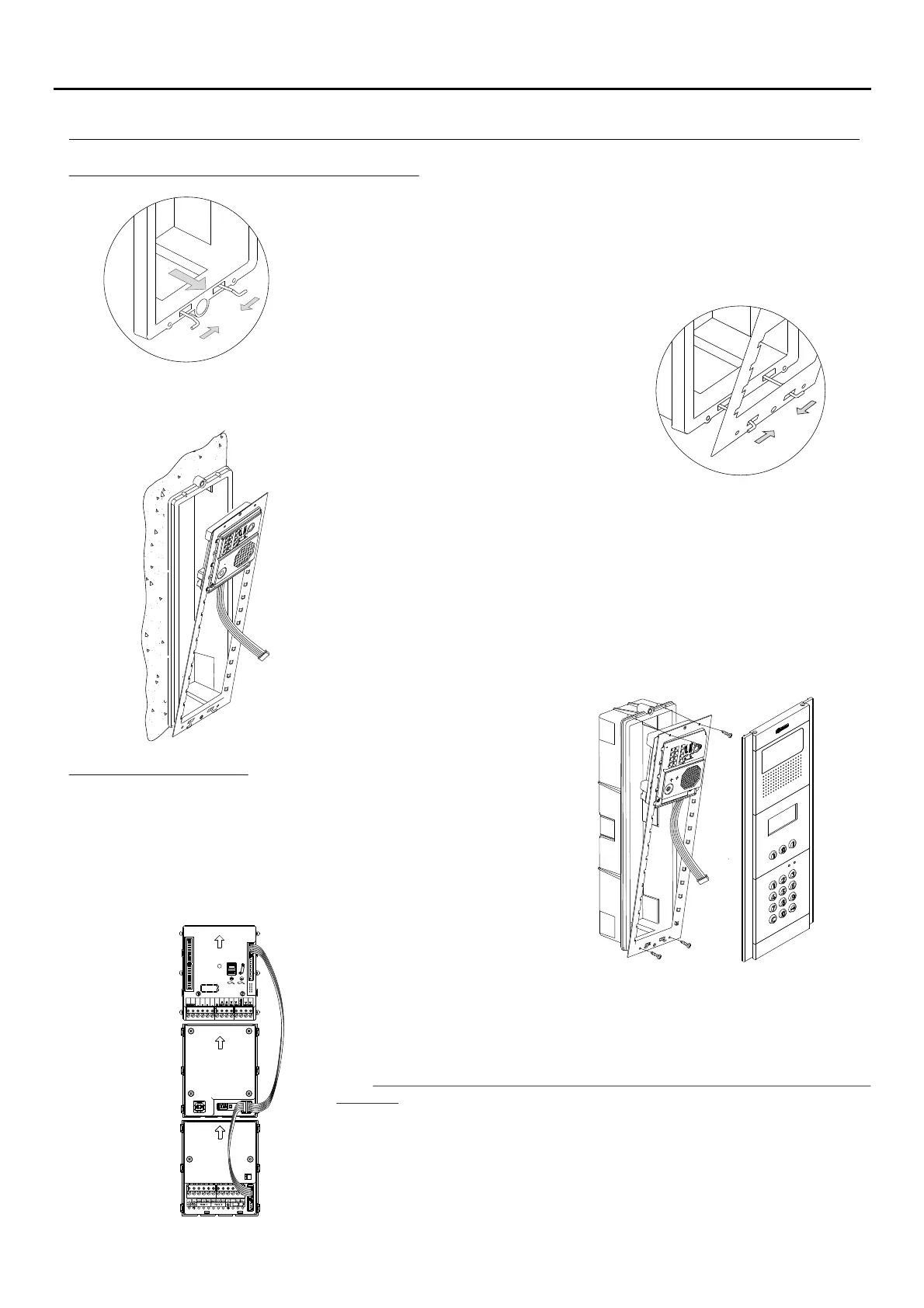
Once the wiring and configuration work is done, fix the
frame to the embedding box using the screws
supplied. Then place the coded module into the frame
to make the Nexa Bus link connection between the
sound module, viewer module and coded module as
indicated in the following point.
The frame can now be tilted horizontally to enable connection and setting of
the sound module, viewer module and access control module. Connect
the Nexa Bus link hose to the sound module and the other modules as
shown in the following section.
To fasten the frame to the embedding box, insert the
spring hinge into the housings provided for this
purpose in the frame, as shown in the drawing.
Insert the spring hinge which attaches to
the product in the embedding box, as
shown in the drawing.

 Loading...