Description of the JP1 jumper:
Tamper alarm mode activated. In this mode, the module's keypad operation
and external buttons are disabled. The LEDs and the keypad's backlight are
turned off and a constant audible alarm and the “P” panic output of the open
collector (3 seconds every minute) are activated. Alarm mode ends when
the JP1 jumper is replaced.
Normal operation, alarm not activated.
The JP1 jumper, located on the right-hand side of the connection block,
activates the tamper alarm.
Description of the SW1 DIP switch (no function):
The SW1 DIP switch is located on the left-hand side of the module.
In this operating mode, the SW1 DIP switch has no function.
110
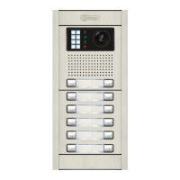
DESCRIPTION OF THE CODED MODULE
The self-testing LEDs are located on the top right-hand side of the front of
the module.
Lock Rapid blink
Correct code
On
Standby
Normal
Operation
On
Off
On (1 second)
Off
Red LED Green LED
Description of the self-testing LEDs:
The access control module features an internal beeper for reproducing operation beeps.
Operation
Error 1 long beep (1 sec)
Key press 1 rapid beep
Duration
Alarm activated 1 constant beep
Description of the beeps:
Correct code
2 rapid beeps
AUDIO AND VIDEO DOOR ENTRY SYSTEM - CODED PANEL WITH DISPLAY

 Loading...