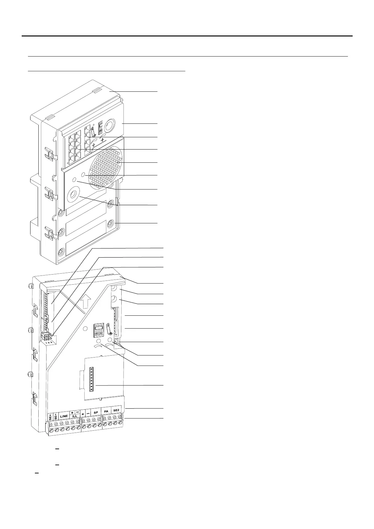
: .Main electric lock connection (max. 12Vdc/270mA) Relay 3.
: Connection Bus (non-polarised).
: Not used.
: Input for external FA-V2Plus power supply (non powered by Nexa Bus link, JP1 set to Pos. 2-3).
: Open door sensor connection.
: Input for external door opening button (Main electric lock).
: Secondary electric lock connection (relay contacts "C" & "NO" ax. 12Vac/1A)., m
SE+, SE
LINE
ILL ILL+,
+,
SP
PA
SE2
Microphone.
Speaker.
Front.
Sound module buttons (x6).
Connection block.
SW4 rotary switch (no function).
Back.
Colour camera.
L s (ED visual indications for people with impaired hearing).
L .EDs
SW3 rotary switch (no function).
CN1 button connector.
Not used.
SW1 DIP switch (no function).
CN NEXA Bus connector.8
Door panel speaker volume control potentiometer.
Telephone speaker volume control potentiometer.
Door panel speaker volume control potentiometer.
Label terminals.
CN5 m dulfor VM-GTWIN vocal synthesis o e.
Telephone speaker volume control potentiometer.
SW DIP switch (no function).2
JP1 jumper: Pos. 1-2 , Pos. 2-3powered by Nexa Bus link connector
external FA-V2Plus power supply. jumper: Not used.JP2
JP2
JP1
Description of the EL632 sound module:/GTWIN
DESCRIPTION OF THE SOUND MODULES
107
AUDIO AND VIDEO DOOR ENTRY SYSTEM - CODED PANEL WITH DISPLAY

 Loading...