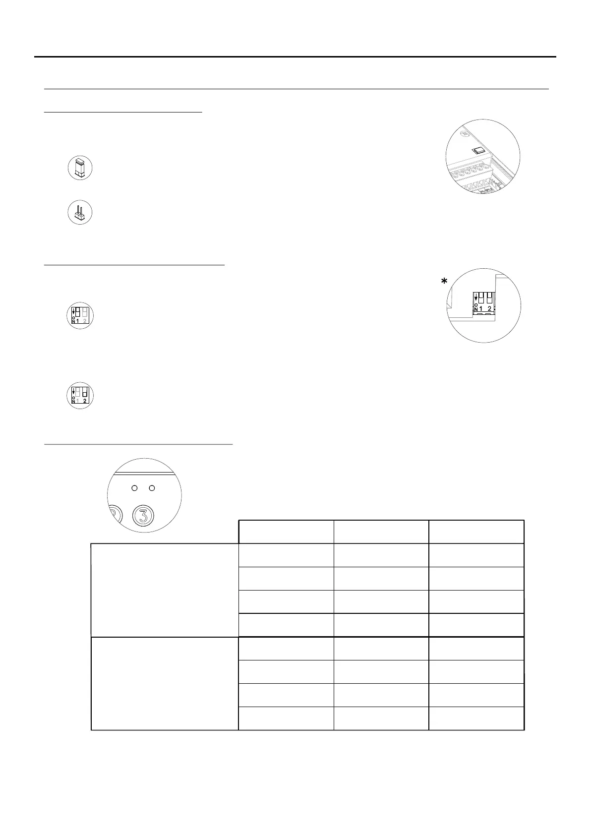
Description of the JP1 jumper:
Tamper alarm mode activated. In this mode, the module's keypad operation
and external buttons are disabled. The LEDs and the keypad's backlight are
turned off and a constant audible alarm and the “P” panic output of the open
collector (3 seconds every minute) are activated. Alarm mode ends when
the JP1 jumper is replaced.
Normal operation, alarm not activated.
The JP1 jumper, located on the right-hand side of the connection block,
activates the tamper alarm.
Description of the SW1 DIP switch:
The SW1 DIP switch is located on the left-hand side of the module.
Use to reset the special installer PIN to the factory code.
Proceed as follows: Set DIP switch 1 to ON. The module will emit 2 beeps and
the green LED on the front will light up for 1 second. Then set the DIP switch to
OFF (the code is now the one assigned at the factory). If the access control module
was locked during this process, the special unlock PIN will also be reset to the factory
code.
Set DIP switch 2 to ON to configure the door panel as a coded door panel.
*
( )
Factory setting.
( )
68
DESCRIPTION OF THE CODED MODULE
AUDIO AND VIDEO DOOR ENTRY SYSTEM - CODED DOOR PANEL
The self-testing LEDs are located on the top right-hand side of the front of
the module.
Lock Rapid blink
Correct code
On
Wrong code
4 rapid blinks
Standby
Normal
Operation
On
Off
On (1 second)
Off
Off
Normal
Slow blink Off
Red LED Green LED
Description of the self-testing LEDs:
Confirm field Slow blink 2 rapid blinks
Programming
mode
Confirm sequence Slow blink 4 rapid blinks
Wrong code 4 rapid blinks Off

 Loading...