CONTENTS
CHARACTERISTICS
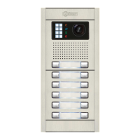
The coded panel with display is configured by adding a display to the coded panel, thereby enabling the actions
performed with the door panel to be viewed. This enables calls to be made using the monitor code or the contacts
residents list. It is also possible to gain access to the building using the numeric code and view, on the door panel
screen, the status of the actions performed.
99
AUDIO AND VIDEO DOOR ENTRY SYSTEM - CODED PANEL WITH DISPLAY
Coded panel with display...........................................................................................................................................98
Contents .................................................................................................................................................................99
Characteristics........................................................................................................................................................99
Description of the Nexa modular door panel .................................................................................................100-101
Description of the sound modules ........................................................................................................................102
Description of the EL632 PLUS P/T - EL642/PLUS sound module....................................................................102
Description of the SW1 - SW2 DIP switch........................................................................................................103
Description of the CN8 Nexa Bus link connector .............................................................................................103
Description of the CN3 function connector.......................................................................................................104
Description of the EL632 R5 P/T - EL642/R5 sound module .............................................................................105
Description of the SW1 DIP switch...................................................................................................................106
Description of the CN7 Nexa Bus link connector .............................................................................................106
Description of the EL632 GTWIN sound module................................................................................................107
Description of the SW1 DIP switch...................................................................................................................108
Description of the SW2 DIP switch...................................................................................................................108
Description of the SW3 & SW4 rotary switch ...................................................................................................108
Description of the CN8 Nexa Bus link connector .............................................................................................108
Description of the N3301/AL - NX3301 coded module......................................................................................109
Description of the JP1 jumper, SW1 DIP switch, self-diagnostic LEDs and beeps ..........................................110
Description of the N3403/AL - NX3403 display modules ....................................................................................111
Description DIP switch .....................................................................................................................................111
Description of the Nexa Bus link connector ......................................................................................................112
Description of the USB connector.....................................................................................................................112
Description of the USB connection LED indicator ............................................................................................112
Installation of the door panel...............................................................................................................................112
Location on the embedding box........................................................................................................................112
Preparing the cable entry, fitting the embedding box and mounting the electronic modules............................113
Fastening the frame to the embedding box ......................................................................................................114
Nexa Bus connection........................................................................................................................................114
Closing the door panel......................................................................................................................................115
Installation FA-PLUS, FA-PLUS/C & FA-GTWIN power supply unit ...................................................................115
Installation of the lock release ............................................................................................................................115
Description of the door panel operation..............................................................................................................116
Programming the door panel ..............................................................................................................................117
Configuartion menu and programming entry and exit.......................................................................................117
System settings menu ...............................................................................................................................118-124
Automatic programming mode for monitors and telephones (Plus y Vista Plus)..............................................124
Access control menu.................................................................................................................................125-129
Residents list menu...................................................................................................................................130-133
Editing with the keypad.....................................................................................................................................134
Programming the Tekna Plus SE monitors.........................................................................................................135
Programming the Tekna R5 Col SU-R5 monitors...............................................................................................136
Programming the Gtwin monitors and telephones ......................................................................................137-138
Programming the T-540/Plus SE telephones .....................................................................................................139
Programming the T-530 R5 SU-R5 telephones..................................................................................................140
Wiring diagrams ..........................................................................................................................................141-145

 Loading...