POWER SUPPLY UNIT INSTALLATION
9
To wall mount the transformer, position the
fastening tabs. Drill two 6mm diameter
holes and insert the wall plugs.
Fix the transformer with the
specified screws.
The power supply unit can be mounted onto a DIN rail (3 elements) by applying slight pressure.
To remove the transformer from the rail, use a flat screwdriver and lever it off, as shown in
the drawing.
Install the transformer in a dry and protected location.
Please note that current regulations stipulate that
the transformer must be protected by a circuit breaker.
DIN 46277
Detail of the TF-104 power supply unit installation:
Red Green
The self-testing LEDs are located on the upper right side of the front of
the module.
Lock Rapid blink
Correct code
On
Wrong code 4 rapid blinks
Standby
Normal
Operation
On
Off
On (1 second)
Off
Off
Normal
Slow blink Off
Confirm field Slow blink
Confirm sequence Slow blink
Wrong code 4 rapid blinks
2 rapid blinks
4 rapid blinks
Off
Red LED Green LED
Programming
mode
DESCRIPTION MODULEOF THE
Description of the self-testing LEDs:
LOCK RELEASE INSTALLATION
Lock release
If the lock release is to be fitted to a metal door, use a Ø3.5mm
drill bit and thread the hole made.
For wooden doors, use a Ø3mm drill bit.
M 4 x 8
DIN-7972
DIN-963
IMPORTANT: the access control module is supplied with two varistors. If
connecting an AC lock release to one of the outputs, fit the
varistor supplied directly to the lock release terminals to
ensure that the module functions correctly.
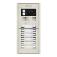
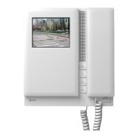
AUDIO AND VIDEO DOOR ENTRY SYSTEM - ACCESS CONTROL

 Loading...