31
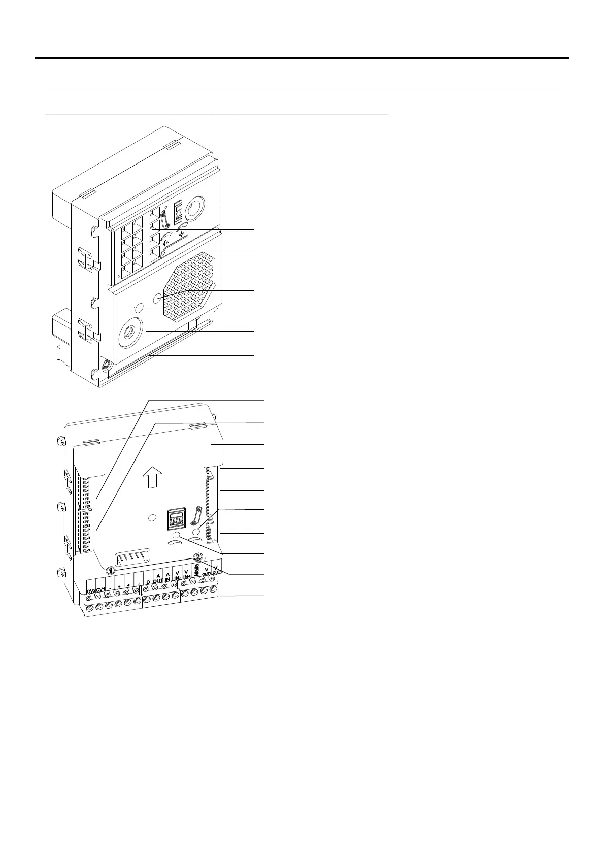
Microphone.
Speaker.
Front.
Sound module buttons (x2).
Connection block.
C 6N button connector.
Back
.
: Contact “C” for electric lock. Relay 3.
: Contact “N.O.” for electric lock. Relay 3.
: Positive, negative.
: Digital communication.
: Audio output communication.
: Audio input communication.
: Balanced video signal input (through twisted pair)
: Balanced video signal output (though twisted pair)
: Coaxial cable .shield
: Video signal input through coaxial cable.
: Video signal output through coaxial cable.
Colour camera. (Only the EL632 PLUS module)P/T
CV1
CV2
+,
D
Aout
Ain
Vi+,Vi-
Vo+,Vo-
Shield
Vi+
Vo+
_
Telephone speaker volume control potentiometer.
LEDs (visual indications for people with impaired hearing)
LEDs. (Only function with EL632 Plus P/T module).
C 8N NEXA Bus connector.
Description of the EL632 PLUS - EL642/PLUS sound module:P/T
S 2 DIPW switch.
Door panel speaker volume control potentiometer.
C 3N function connector.
S DIPW1 switch.
Button number.
AUDIO AND VIDEO DOOR ENTRY SYSTEM - ACCESS CONTROL
DESCRIPTION OF THE SOUND MODULES
Telephone speaker volume control potentiometer.
Door panel speaker volume control potentiometer.

 Loading...