DESCRIPTION OF THE SOUND MODULES
66
AUDIO AND VIDEO DOOR ENTRY SYSTEM - CODED DOOR PANEL
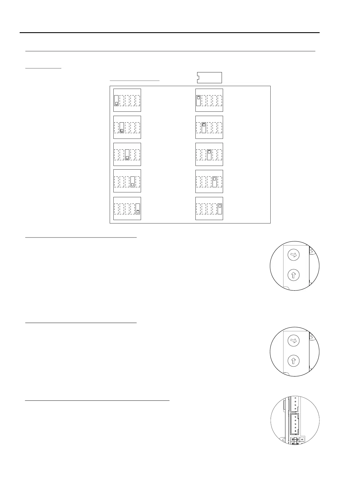
Description of the CN8 Nexa Bus link connector:
The CN8 Nexa Bus link connector is located on the upper left side of the back of the sound
module.
Connect the cable supplied with the module to other modules using the NEXA Bus:
ðN3403/AL: Connect the module to provide the system with a display viewer.
ðN3301/AL: Connect the module to provide the system with access control and a coded door panel.
ðEL3002: Connect to the bus to power information panels (maximum unit).1
Not : ( FA-V2Plus , p ),e With power supply see age 64 3 more Nexa modules can be connected.external power supply"
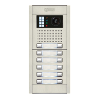
AUX
ON DIP
4321 5
Master
ON DIP
4321 5
Slave
ON DIP
4321 5
Slave 0
ON DIP
4321 5
Slave 1
ON DIP
4321 5
Door lock release
free
ON DIP
4321 5
Door lock release
privacy
ON DIP
4321 5
On
ON DIP
4321 5
Off
ON DIP
4321 5
Camera lights
Off
Door panel type
Slave door panel
address
Door lock release
Camera lights
ON DIP
4321 5
Camera lights
On
Interruption
SW2 DIP-SWITCH:
*
( )
*
( )
*
( )
*
( )
*
( )
Camera lights: The camera lights may be turned off if illumination in the surrounding environment is sufficient at night.
The configuration rotary switch is located on the upper right side of the back of the soundSW3
module.
Description of the SW3 rotary switch: (Guaranteed conversation time).
2
9
0
5
1
SW2
SW4
SW3
3
4
6
7
8
2
9
0
5
1
3
4
6
7
8
*
( )
The posistion of the rotary switch, determines a guaranteed conversation time, i.e.SW3
extends the busy time from the answer onwards. (Note: Call time is max. 60 seconds).
Pos. 0 = 1 s Pos. 1 = 10 s Pos. 2 = 20 s Pos. 3 = 30 s ( )
Pos. 4 = 40 s Pos. 5 = 50 s Pos. 6 = 60 s Pos. 7 8 = 70 sy
Pos. 9 = NOT ALLOWED.
Not :e The guaranteed conversation time has to be configured the same in all the door panels present in the system.
*
*
( )
Factory default.
The configuration rotary switch is located on the upper right side of the back of the soundSW4
module.
Description of the SW4 rotary switch: (Door lock release time).
2
9
0
5
1
SW2
SW4
SW3
3
4
6
7
8
2
9
0
5
1
3
4
6
7
8
*
( )
The position of the rotatory switch, determines the activaton time of the main door lockSW4
(SE+, SE- terminals).
Pos. 0 = 1 s ( ) Pos. 1 = 10 s Pos. 2 = 20 s Pos. 3 = 30 s
Pos. 4 = 40 s Pos. 5 = 50 s Pos. 6 = 60 s Pos. 7 = 70 s
Pos. 8 = 80 s Pos. 9 = 90 s
*
*
( )
factory default.
Continued from previous page
*
( )
Factory default.

 Loading...