28 / 80
33028_mc_28_Teil2_jh
Column 1
The first column lists the control outputs.
The numbered servos refer to the servos connected to the corre-
sponding receiver outputs, assuming that the transmitter and
receiver outputs have not been switched. A change in the control
mode does not influence the numbering of the servos.
Column 2 "Rev"
This option controls the servo direction to the specifics of each
model.
Select with the SET button and t u: "=>" normal, "<=" reverse
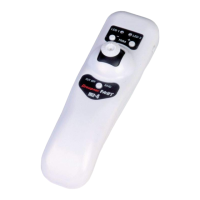
Column 3 "Cent"
You can set the servo centre in a ±125 % area within the servo travel
of max. ±150 %. The servo is always adjusted independently of all
other trim and mix settings.
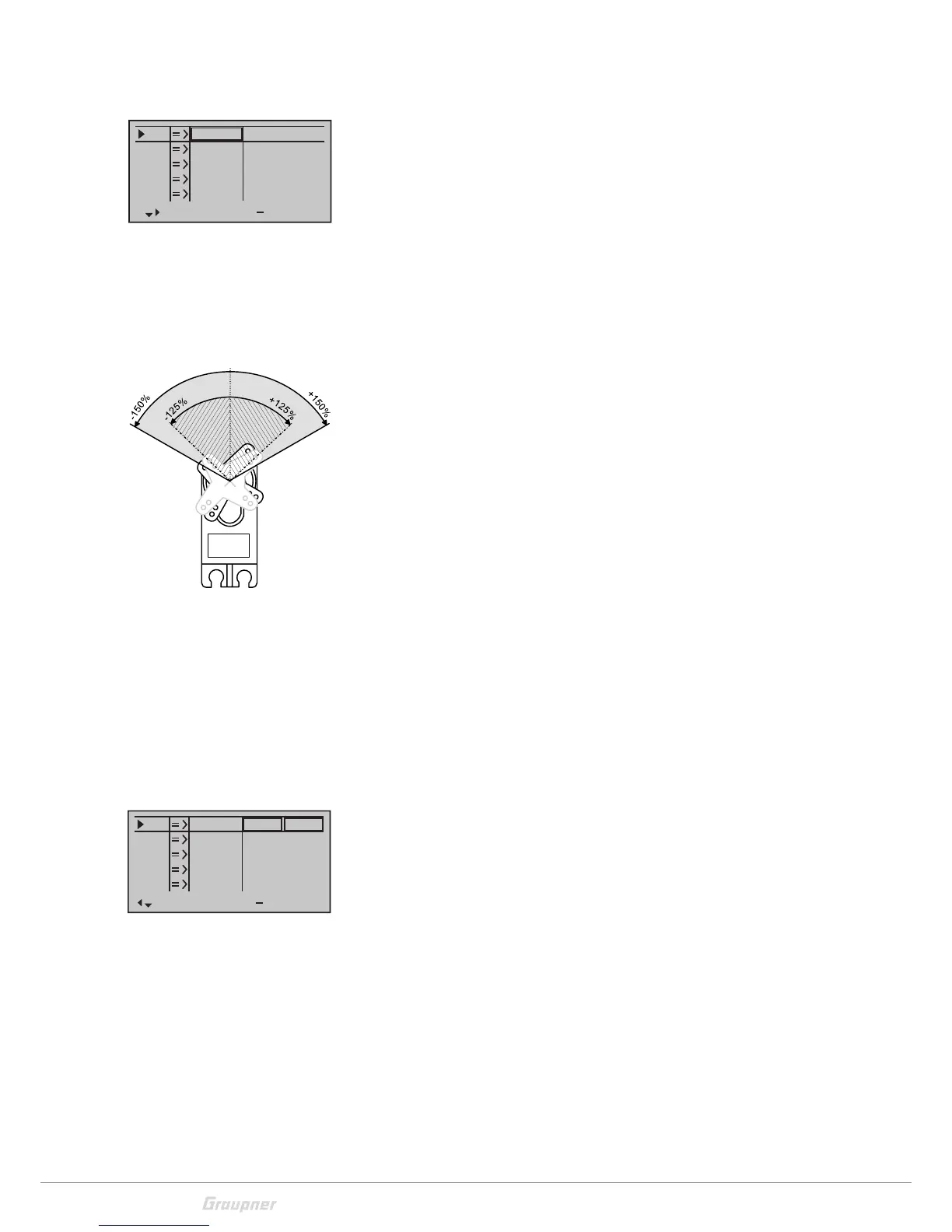
Column 4 "– Trv +"
In this column you can set the servo travel for both sides, together
or separate for each side. The setting range is 0 to150% of the nor-
mal travel. The set values always refer to the settings in the column
"Centre".
Symmetrical travel setting:
Move the related control element (control stick, proportional con-
trol or switch) into a position in which both sides of the travel adjust-
ment are surrounded by the marking frame.
Asymmetrical travel setting:
Move the related control element (control stick, proportional con-
trol or switch) into a position in which the single side of the travel
adjustment is surrounded by the marking frame.
Column 5 "Lim"
In this column you can limit the servo travel. To reach the column "-
lim +", move the marking frame with the selection button to the
right over the column "- Trv +".
Symmetrical or asymmetrical setting of the limit as explained in the
"– Trv +" section.
S1
S2
S3
R ev cent
+
tr v
0%
0%
0%
100%
100%
100%
100%
100%
100%
0%
0%
100%
100%
100%
100%
S4
S5

 Loading...