27 / 80
33028_mc_28_Teil2_jh
Ailerons/Flaps
In this line you can select the number of servos installed in the wings.
The following table shows the control channels to which the servos
must be connected.
Control surfaces
count
Occupied control channel
1AILE 2
1AILE 1FLAP 2 | 6
2AILE 2 + 5
2AILE 1FLAP 2 + 5 | 6
2AILE 2FLAP 2 + 5 | 6 + 7
2AILE 4FLAP 2 + 5 | 6 + 7 / 9 + 10
4AILE 2FLAP 2 + 5 / 11 + 12 | 6 + 7
4AILE 4FLAP 2 + 5 / 11 + 12 | 6 + 7 / 9 +
10
According to this scheme, the required mixers and the respective
setting possibilities are activated in the "Wing mix" menu.
Brake offset
This line sets the offset point in which the control surfaces (AILE/
FLAP) are completely retracted or closed.
The function will be assigned to the related input in the right column.
Assign an Offset_point:
Move the control element of the input CH1-control stick, input 1,7,8
or 9, in the position where the control surfaces have to be retracted
or closed. Tap on the SET button to save the "Offset" point.
A “+” extends the flaps for brake offset values when the correspond-
ing control element is moved from front to rear toward the pilot.
A “-” extends the flaps for brake offset values when the correspond-
ing control element is moved from back to front away from the pilot.
Servo adjustment
In this menu the servo parameters are set for each servo: servo
direction, neutral point, servo travel and limits. Start the servo set-
tings in the left column.
Tail type
Motor at C1
normal
None
Aile/flaps
1AIL
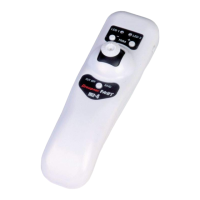
Model type
Brake Off In1+100%
SEL
Tail type
Motor at C1
normal
None
Aile/flaps
1AIL
Model type
Brake Off In1+90%
SELSTO
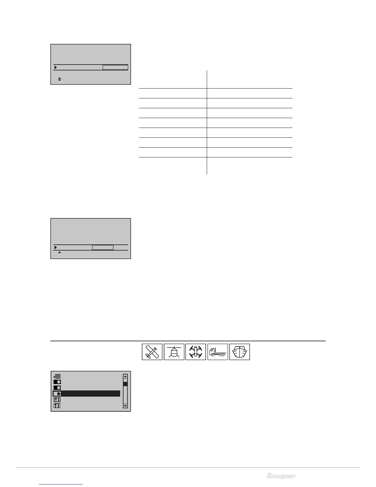
Suppress models
Base setup model
Control adjust
Model type
Servo adjustment
Stick mode

 Loading...